Dean H
-
Posts
370 -
Joined
-
Last visited
-
Days Won
44
Content Type
Profiles
Forums
Gallery
Everything posted by Dean H
-
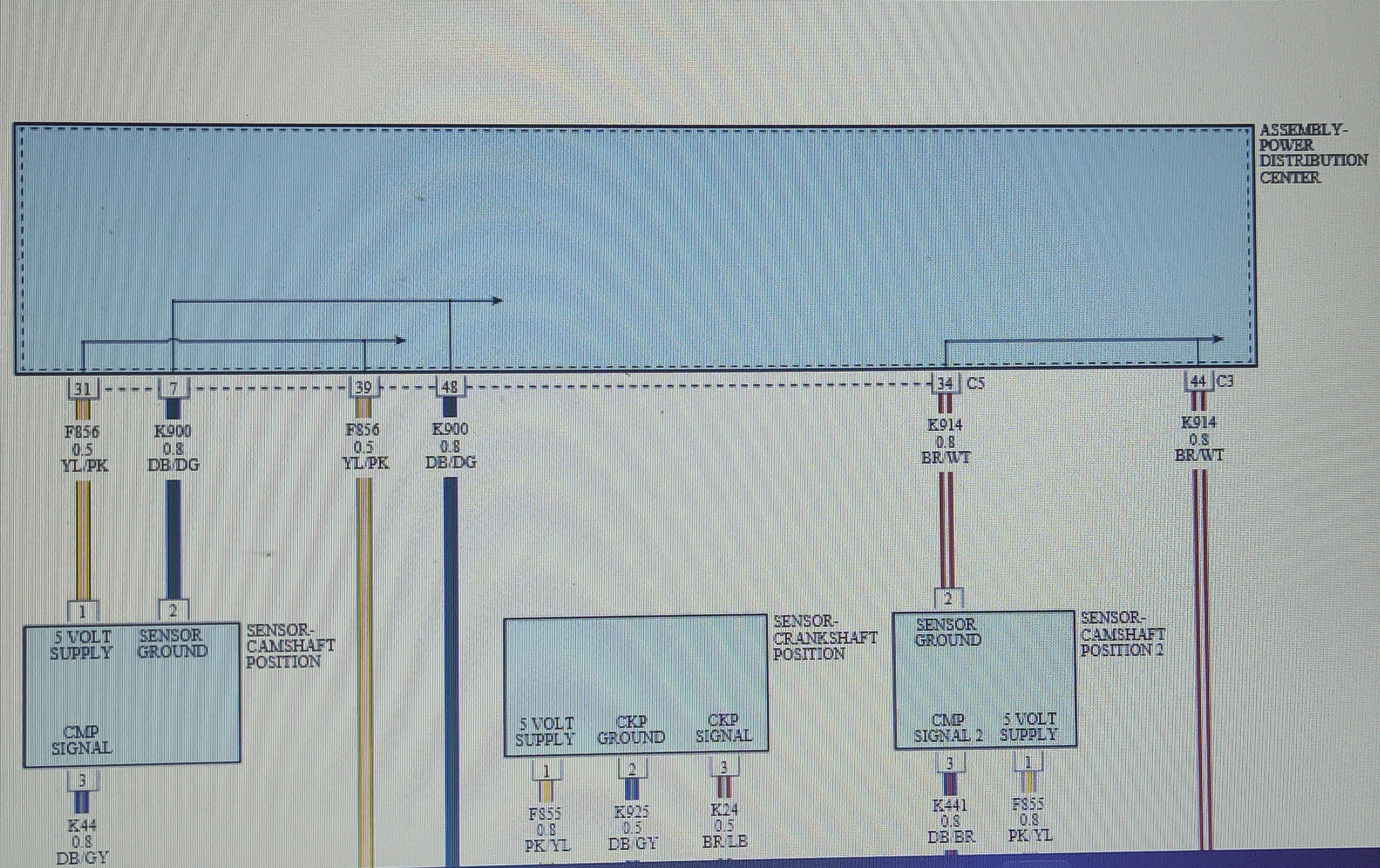
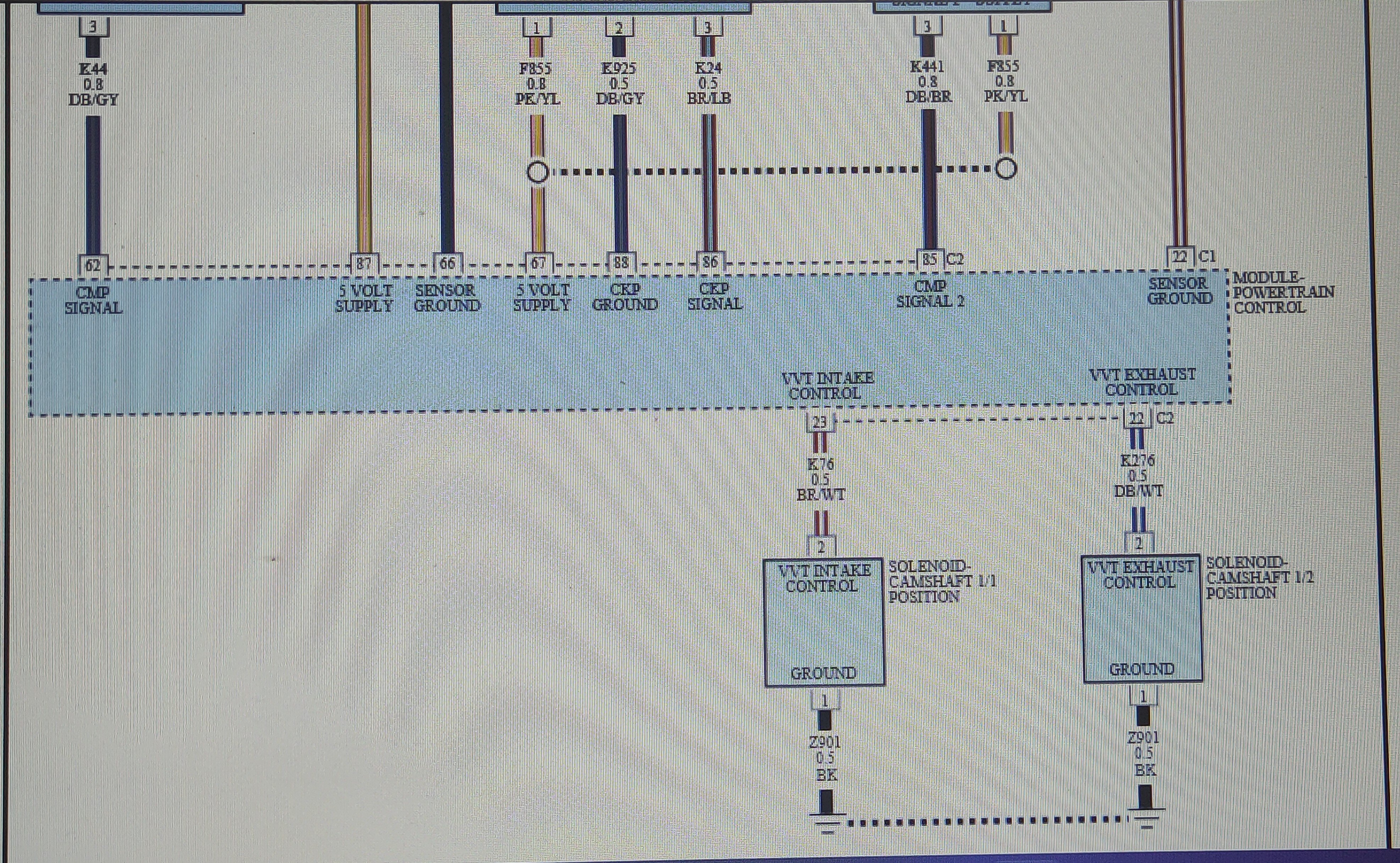
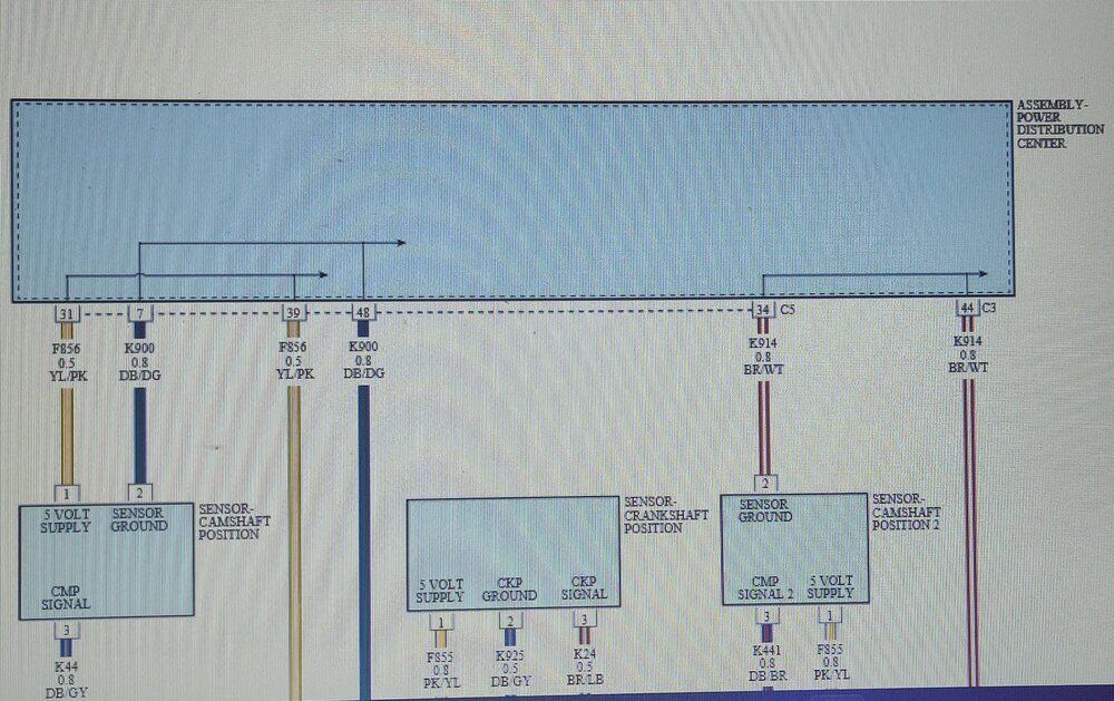
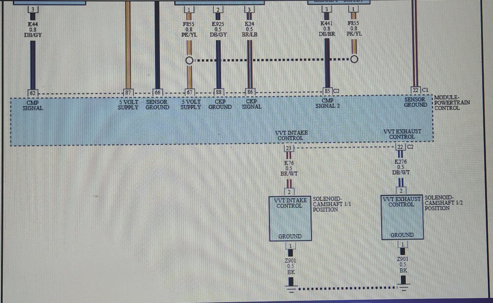
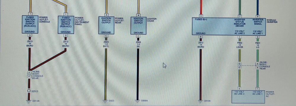
Crankshaft position sensor wiring diagram.
-
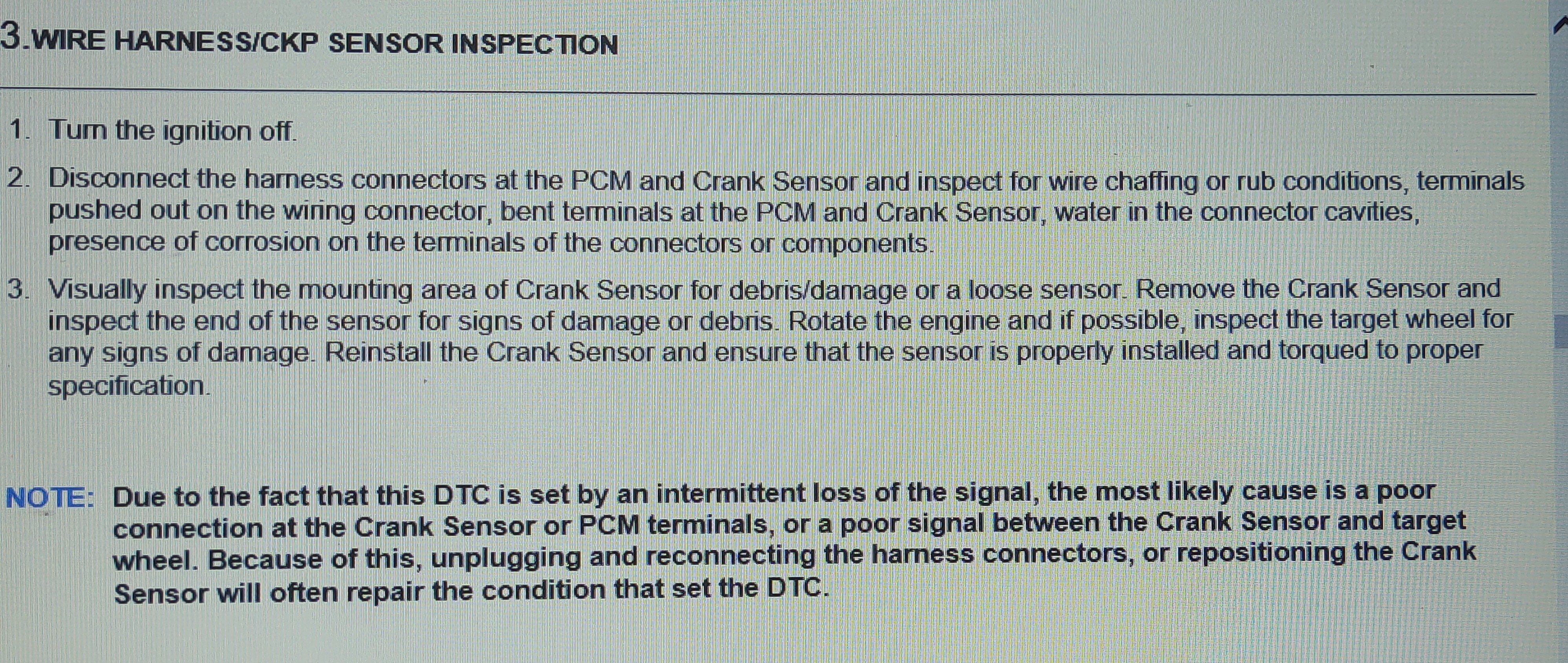
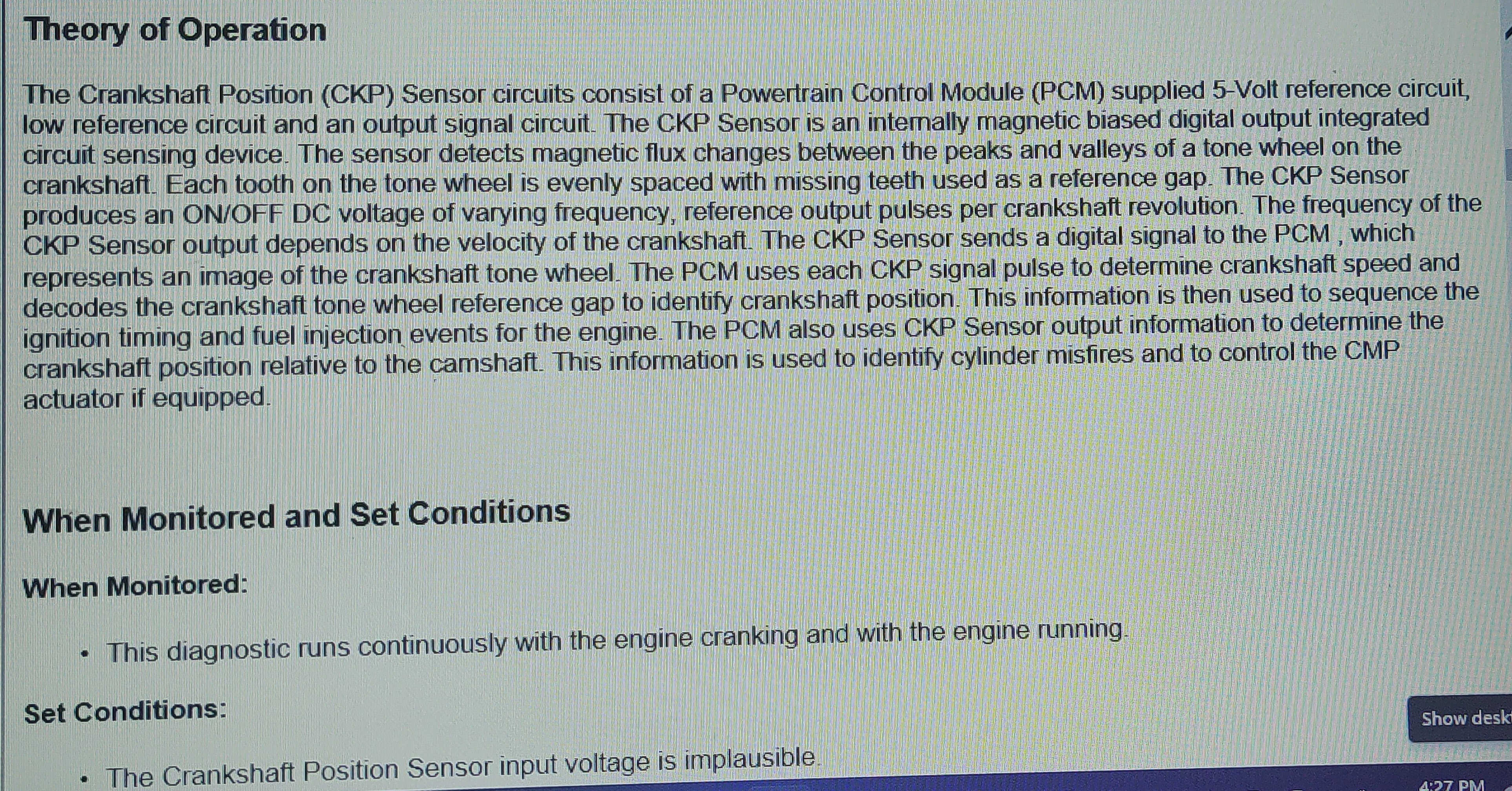
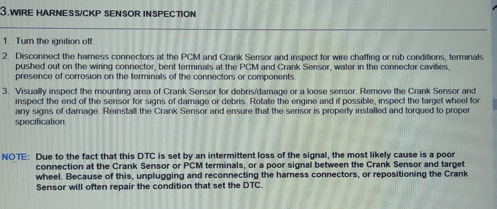
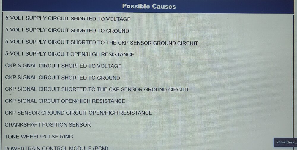
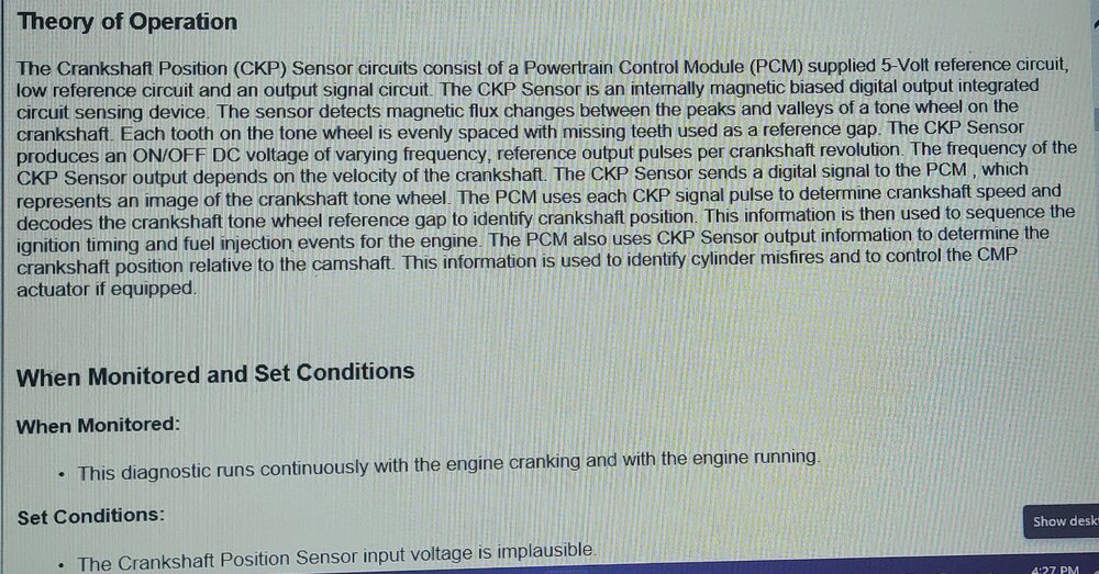
Crankshaft position sensor code.
-
Here is the codes break down. 2016 DJ service CD. B2193-00 - Battery sensor internal short. Replace battery sensor. P0113 - Intake air temperature sensor 1 circuit voltage high. -IAT SENSOR -WIRE ISSUE P0335 Crankshaft position sensor circuit See following post. U0100-00. BCM lost communication with PCM See following post B1C19 - passenger headrest control circuit high B1C13 - Driver headrest control circuit high B1408-13. rear left speaker circuit open B210a-16, Telematics gateway (TGW) system voltage circuit voltage below threshold. B210d-16 B210D - ORC restraint controller Battery Voltage Low.
-
I would like to know if the engine cranks over? Be specific as to the speed and how it sounds. Is it possible to post a recording of it cranking?
-
2010 Dodge Journey keeps draining battery
Dean H replied to FedUp7's topic in Electrical, Battery & Charging
This shows the interior fuse box. https://www.startmycar.com/us/dodge/journey/info/fusebox/2011 Fuse #131. HFM -
2010 Dodge Journey keeps draining battery
Dean H replied to FedUp7's topic in Electrical, Battery & Charging
Find a pull the HFM fuse. Interior fuse box by glove box. Check that your glove box light isn't staying on as well. -
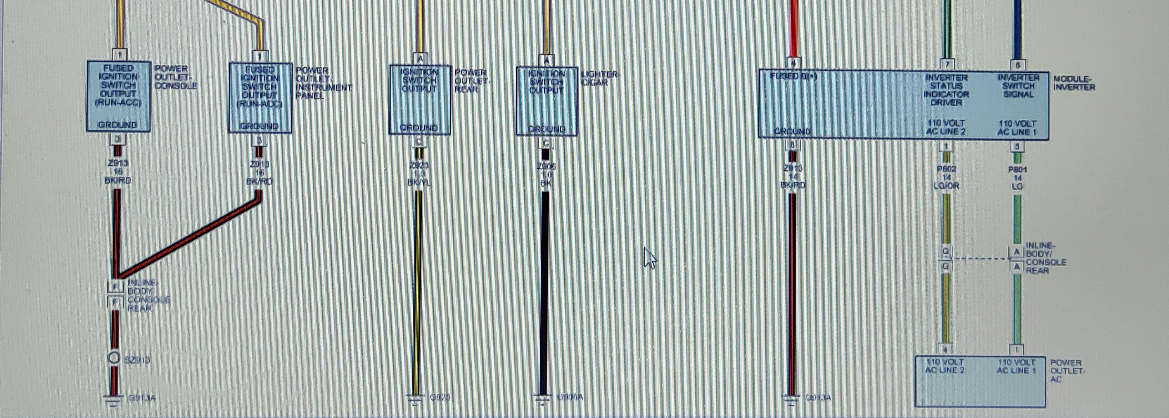
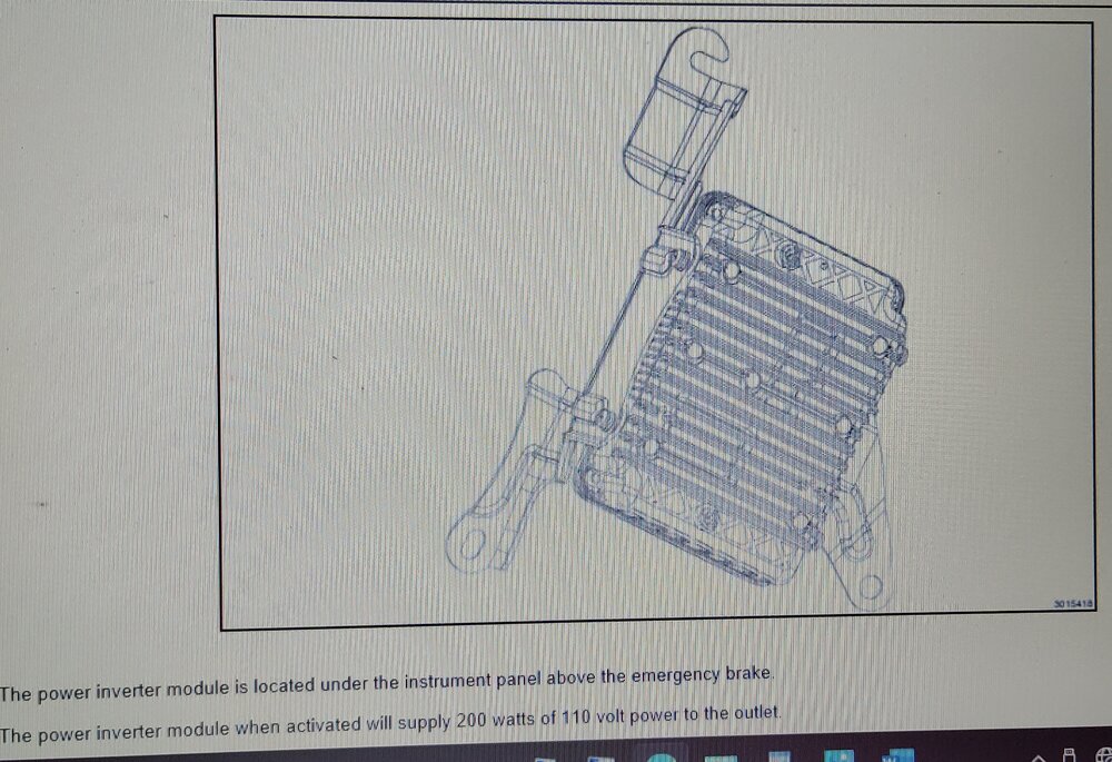
2016 DJ power inverter information.


-
2012 SXT 3.6L starter change: nightmare job ?
Dean H replied to danyboy's topic in Electrical, Battery & Charging
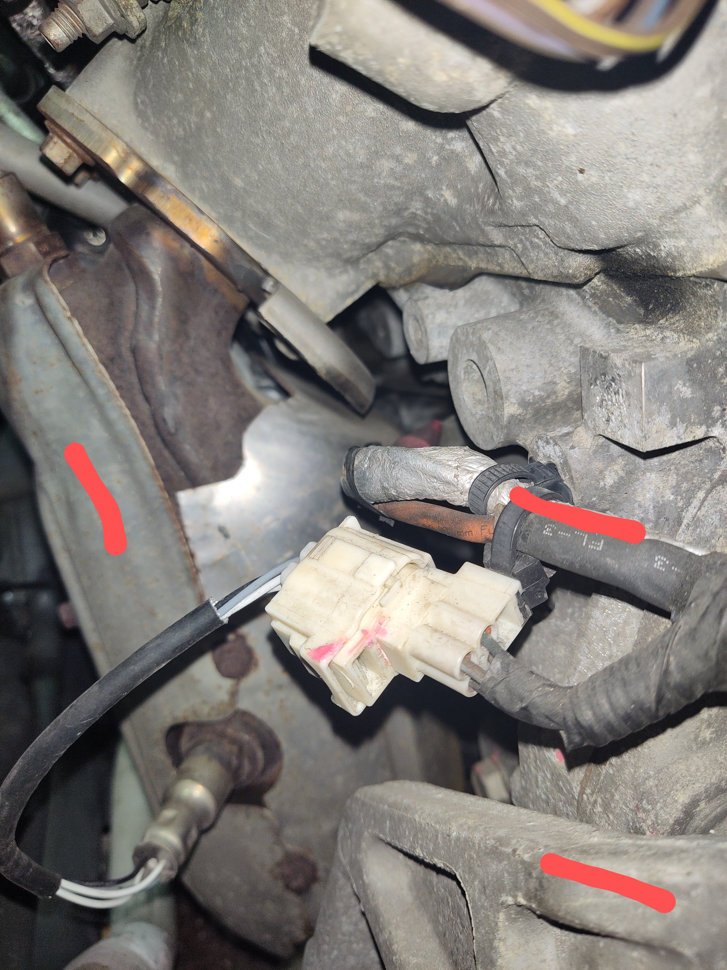
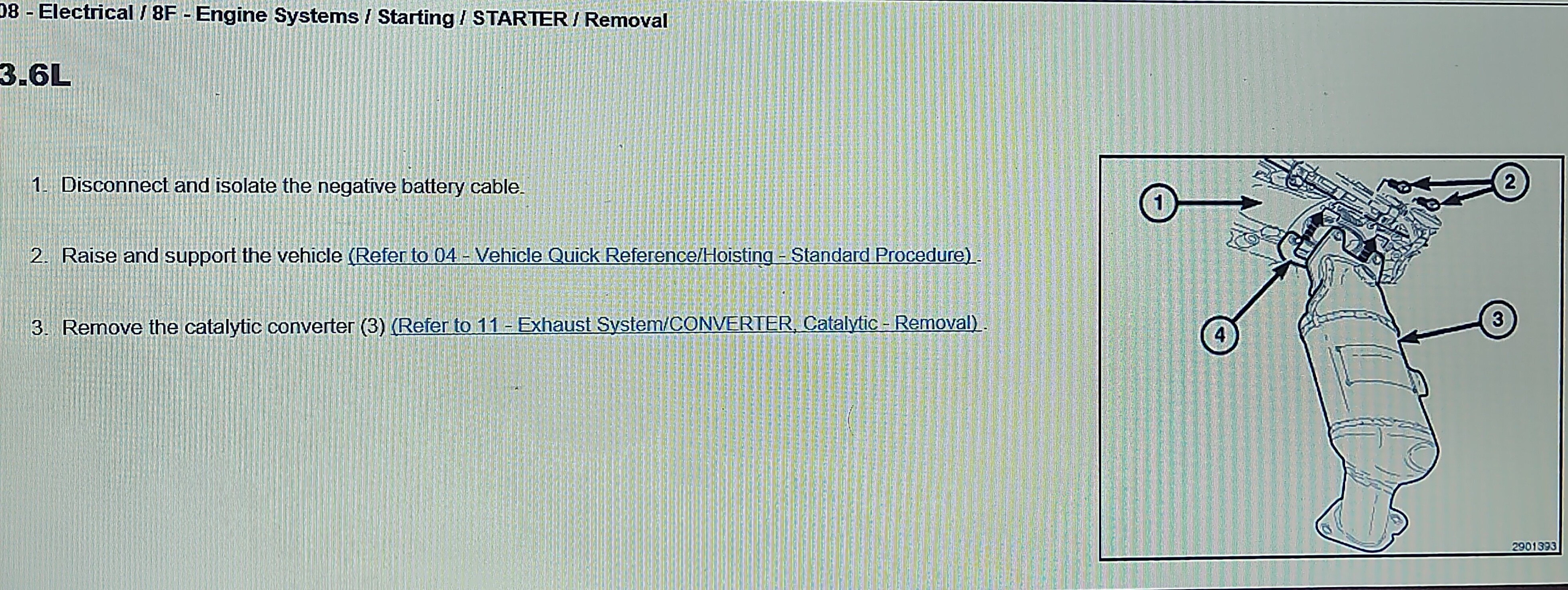
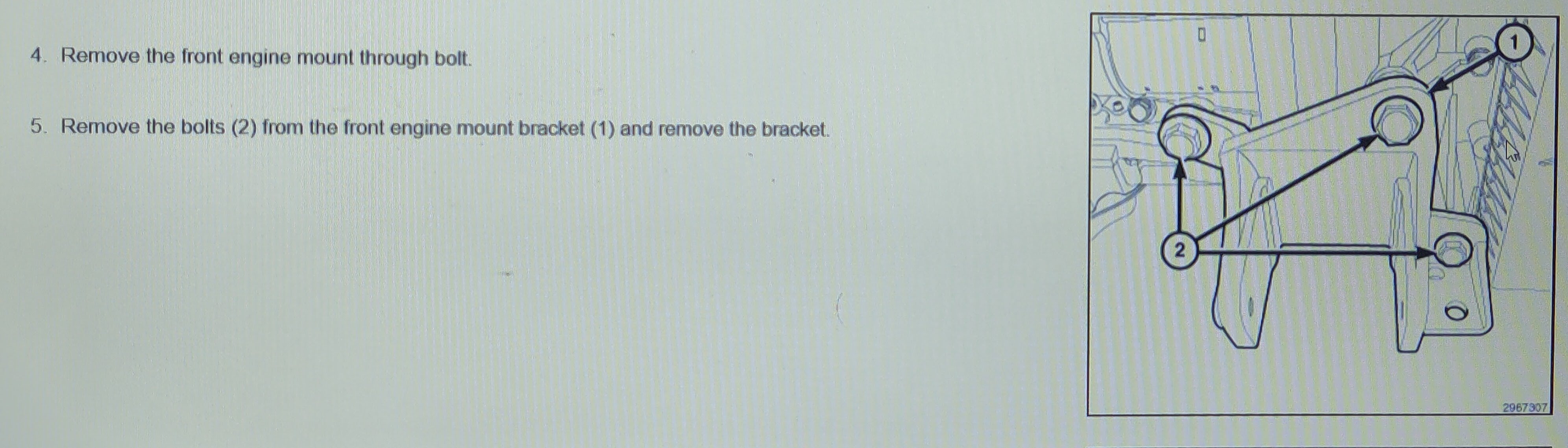
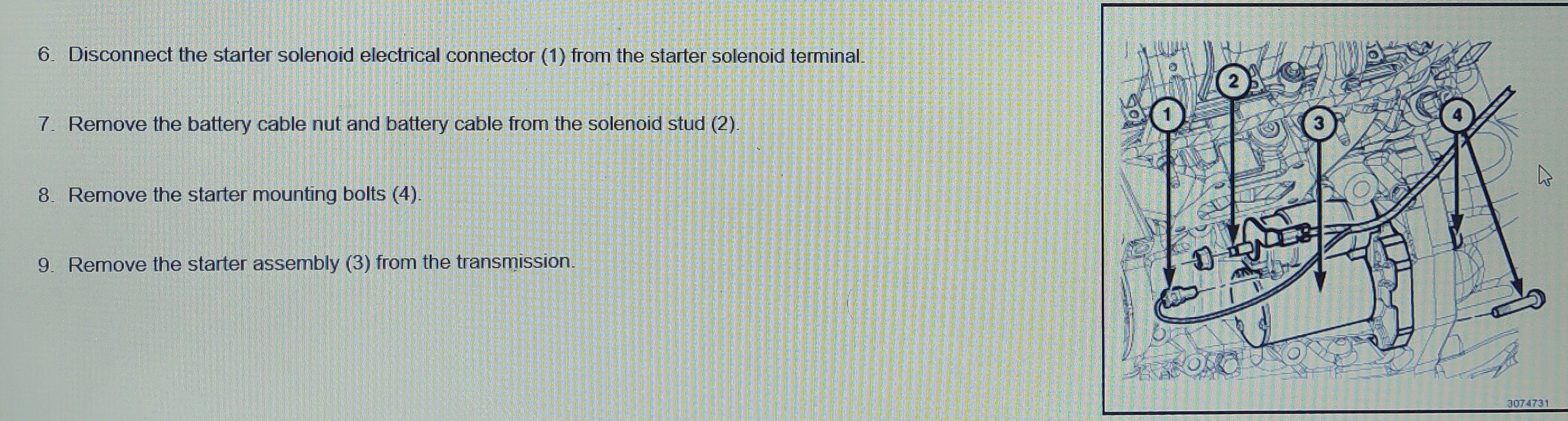
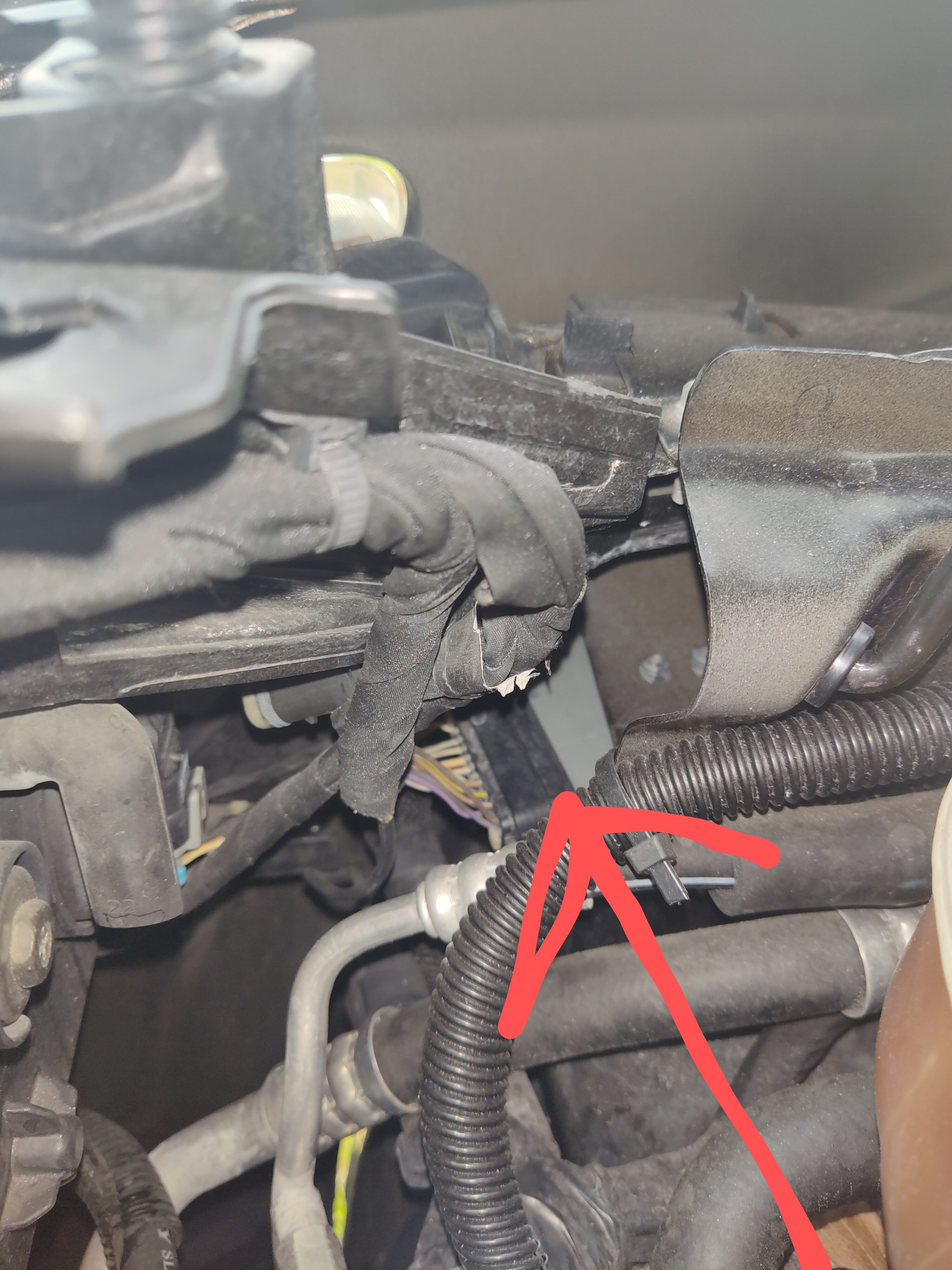
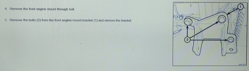
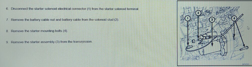
To replace the starter on a 3.6L. Everything you remove comes out from the top. The only thing you disconnect under the car is the catalytic converter flange bolts. Remove the front catalytic converter. Remove the motor mount bracket bolted the the engine. Located in front of the starter. The 2016 DJ service CD. Doesn't mention you have to support the engine before removing the motor mount bracket. You might have to remove the air filter box and air intake that goes up over the radiator. In this picture, I marked the starter cable, catalytic converter and the motor mount bracket.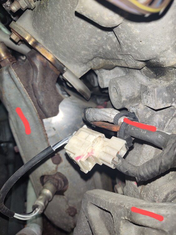
-
2012 SXT 3.6L starter change: nightmare job ?
Dean H replied to danyboy's topic in Electrical, Battery & Charging
2016 DJ Service CD. Read my post after this one.
-
Dodge Journey service manual 2009-2011 and 2012-2016
Dean H replied to mojo's topic in Maintenance & D.Y.I.
Try this - https://www.ebay.com/itm/126665078024?mkcid=16&mkevt=1&mkrid=711-127632-2357-0&ssspo=WLBXaZbpSKC&sssrc=4429486&ssuid=i3l8BOlITT-&var=&widget_ver=artemis&media=COPY -
2012 SXT 3.6L starter change: nightmare job ?
Dean H replied to danyboy's topic in Electrical, Battery & Charging
Hi guys, I only did a starter cable upgrade. I only removed the starter cable nut. That alone was a pain and time consuming. -
The fuses to check are on the interior fuse box. Located below and to the right of the glove box. F128 radio F126 audio amplifier If okay. Try resetting them both by removing the fuses. Wait then reinstall.
-
2016 Dodge Journey 2.4 fuel pressure spec is: 58 psi + or - 5 psi.
-
Do you have the stock Dodge radio? What aftermarket equipment do you have?
-
My friend installed my battery backwards.
Dean H replied to JohnsterMonster86's topic in Electrical, Battery & Charging
To fix this issue- Install a new fusible link or fuse on the Dodge, 4 gauge alternator cable. OR- Run a a new, separate 4 gauge cable. With a circuit breaker or fuse matched to the 4 gauge cable amperage rating. Run it from the TIPM positive battery stud. To the alternator battery stud. Disconnect and seal off the old cable down at the starter. -
Follow 5rebel9's directions. Read my post and whole thread below, regarding the battery and battery sensor. Everything you need to know is covered in it. https://www.dodgejourneyforum.com/topic/18210-electrical-system-fyi-battery/
-
My friend installed my battery backwards.
Dean H replied to JohnsterMonster86's topic in Electrical, Battery & Charging
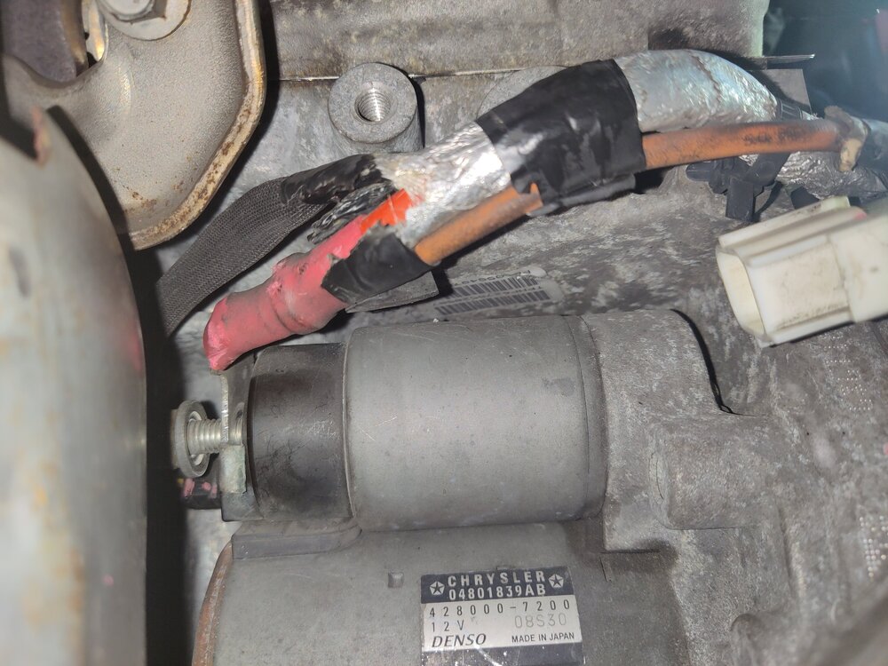
For clarification purposes here is my picture of the starter and cables in question. The top red cable is the battery voltage feed cable from the TIPM (under hood fuse box). The lower dirty orange one is the fusible link that connects to the alternator stud. Your fusible link is blown. I believe you have the 3.6 V6 engine. Please verify this fact.
-
Ambient Air Temperature Sensor Code P0070
Dean H replied to MarkyB's topic in Electrical, Battery & Charging
The red clip has to pulled down to release the wire harness. Can you tell me the code title for P0070? So I can look it up. -
Ambient Air Temperature Sensor Code P0070
Dean H replied to MarkyB's topic in Electrical, Battery & Charging
Your going to remove the complete sensor from the front clip first. Then try to separate the connector. It is held in by a push in trim thing. Using trim removal tool with the slot in it will help While pulling it away from the front clip. Pull on the the left side then right side. Going back and forth. Go easy. The connector is going to be a royal pain in the -beep-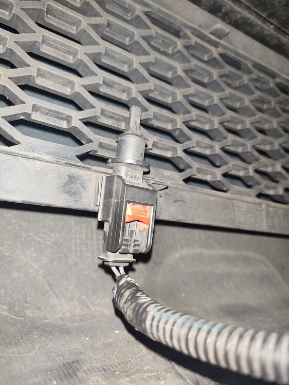
-
My friend installed my battery backwards.
Dean H replied to JohnsterMonster86's topic in Electrical, Battery & Charging
So what you have is the top cable. That is the battery voltage feed from the TIPM- (under hood fuse box). To the starter. The lower cable carries the battery voltage to the alternator from the starter stud. The smaller section is a fusible link. It protects the cable like a fuse does. Use a multimeter and check for battery voltage at the alternator stud. To find out if this cable is a problem. Here is a picture of my 3.6 starter cable on top and alternator cable fusible link below it.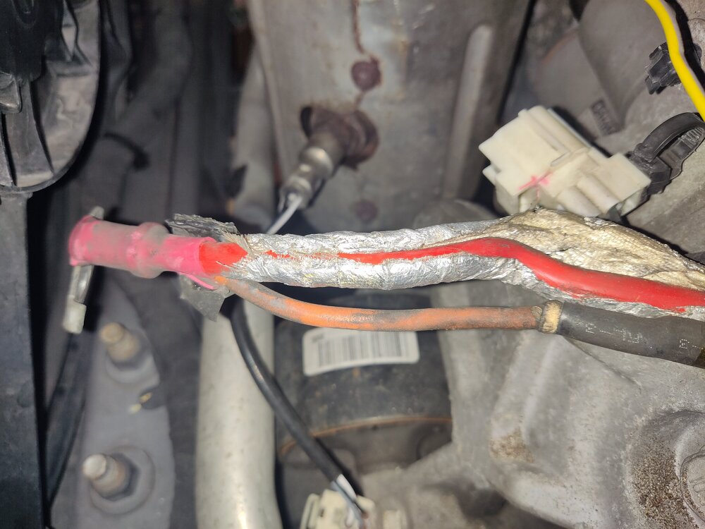
-
Ambient Air Temperature Sensor Code P0070
Dean H replied to MarkyB's topic in Electrical, Battery & Charging
Connector, yes. Easy access - BMC to the right of the glove box.
-
Ambient Air Temperature Sensor Code P0070
Dean H replied to MarkyB's topic in Electrical, Battery & Charging
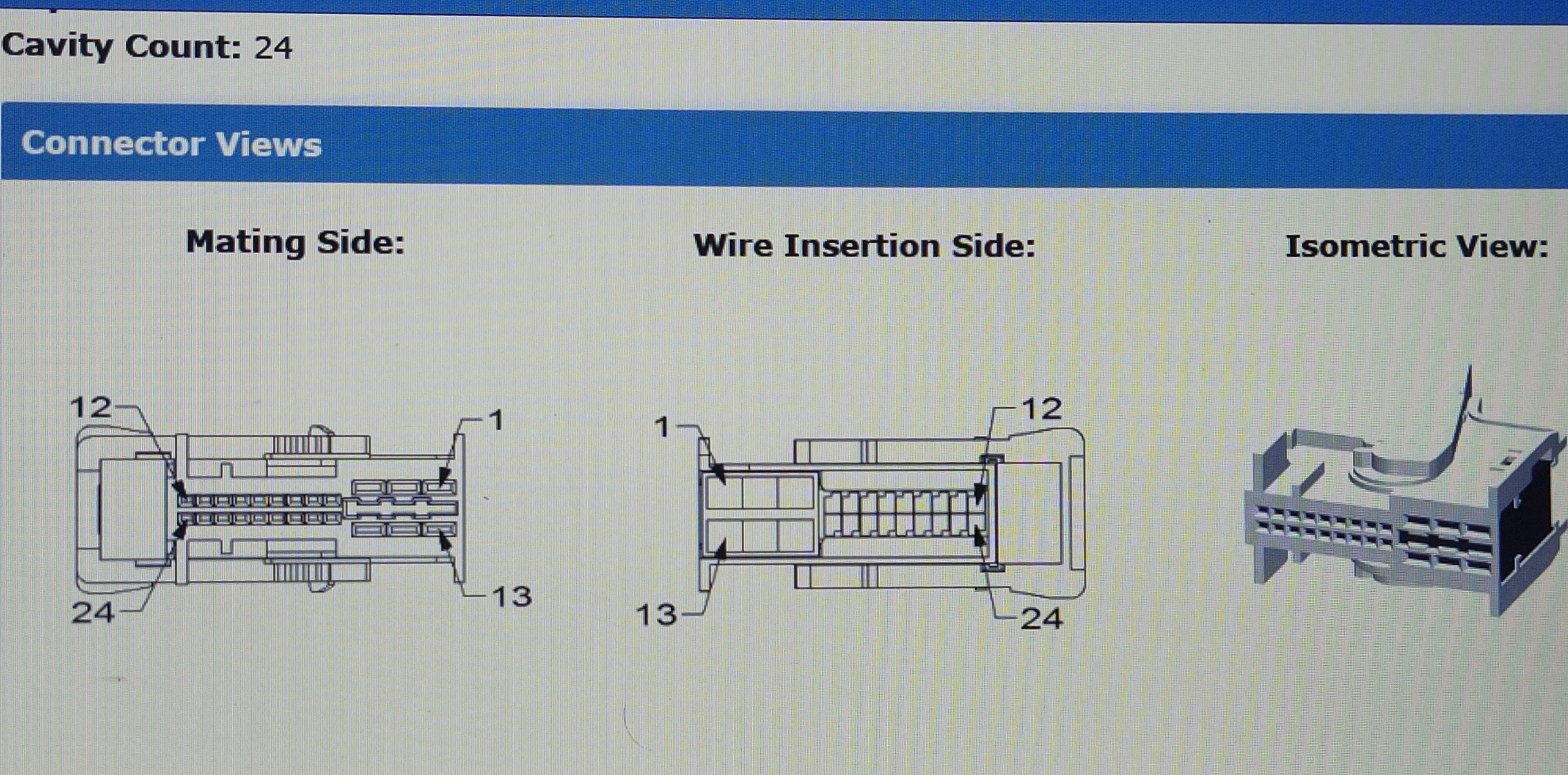
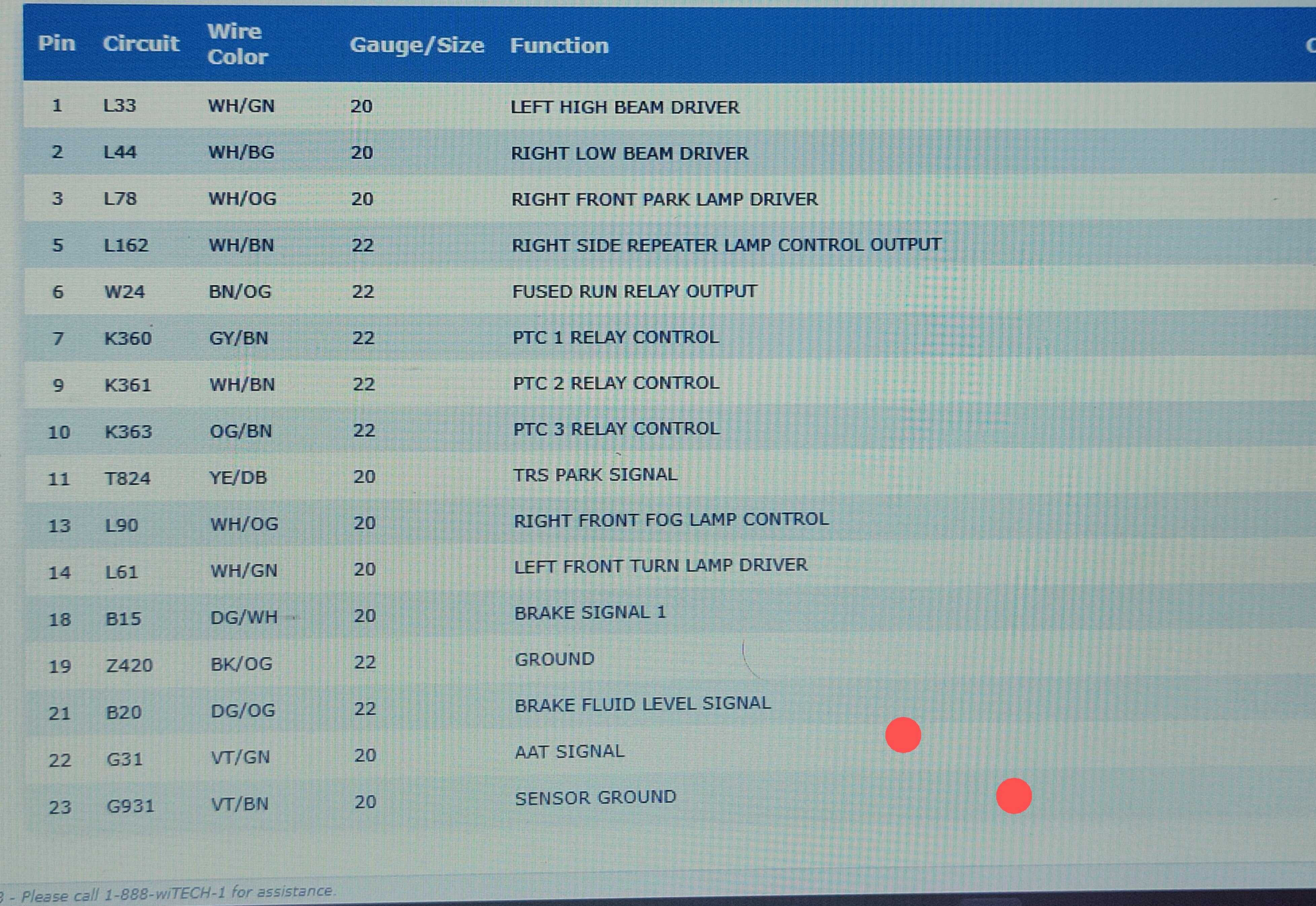
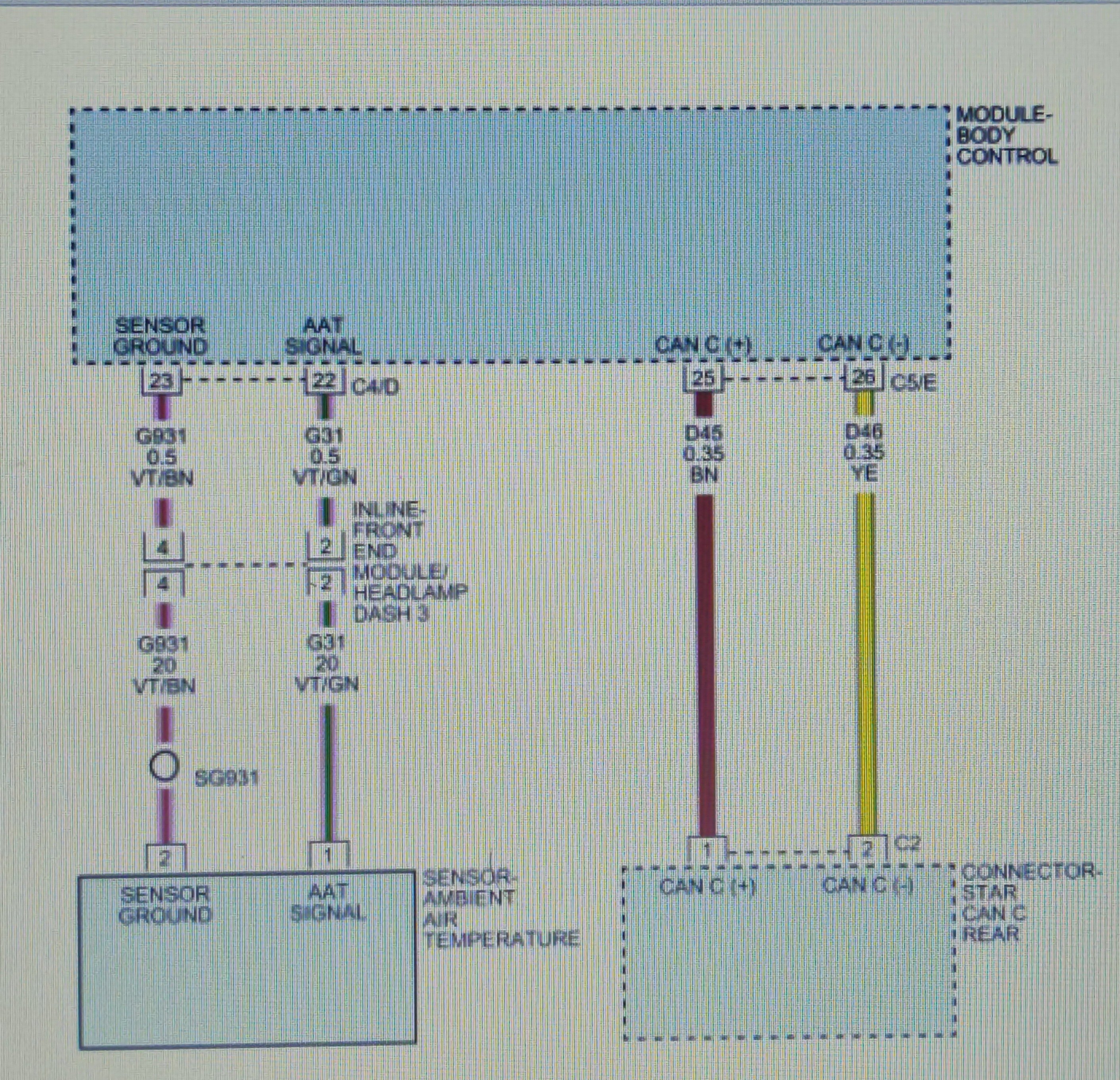
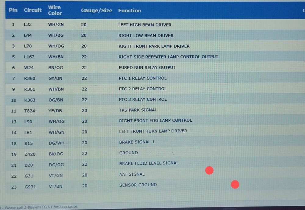
Circuit from front end module connector to BCM. BCM CONNECTOR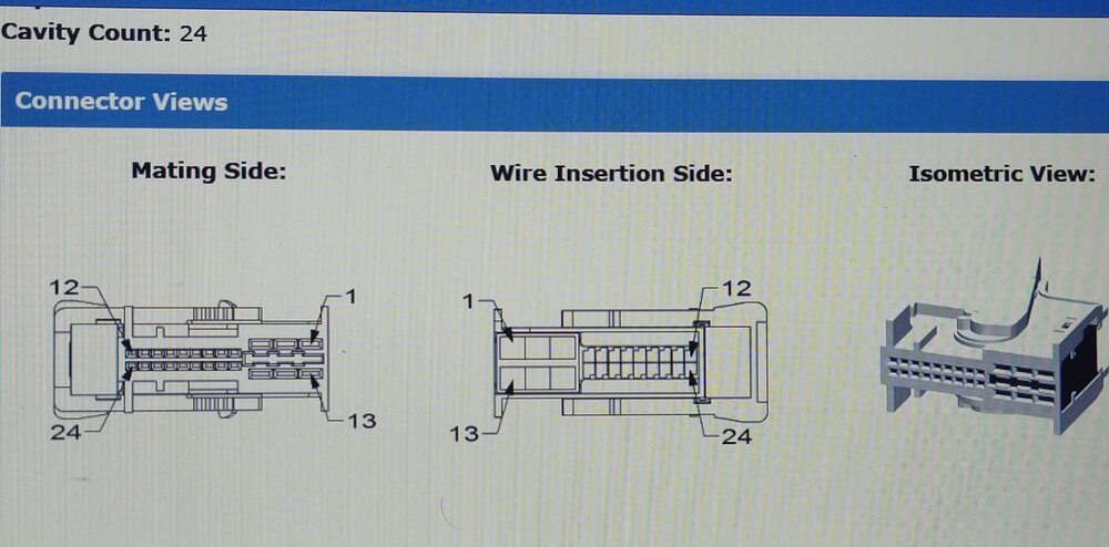
-
Ambient Air Temperature Sensor Code P0070
Dean H replied to MarkyB's topic in Electrical, Battery & Charging
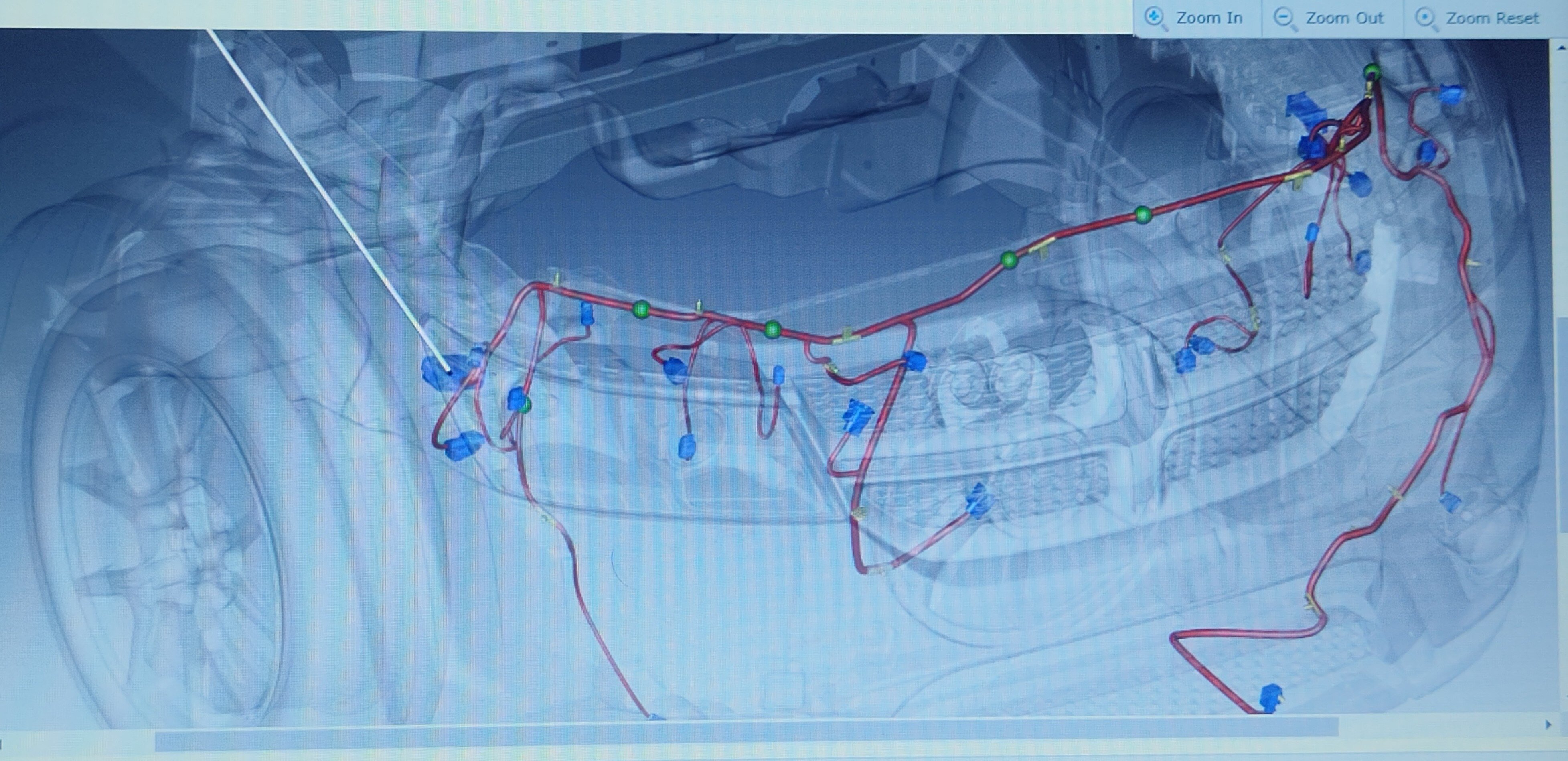
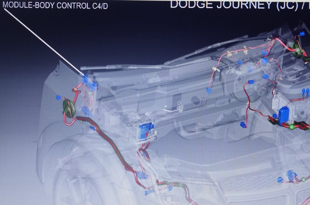
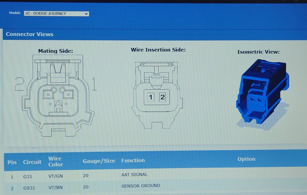
2016 DJ service CD The connector the circuit goes to, is the one at the end of the white line. Inline front end module connector.

-
Alternator, Battery, ETC....HELP PLEASE!!
Dean H replied to Smitty21's topic in Electrical, Battery & Charging
First read this post- https://www.dodgejourneyforum.com/topic/18354-battery-saver-mode/ Start with your battery - Read this post below- https://www.dodgejourneyforum.com/topic/18210-electrical-system-fyi-battery/ After the battery post instructions and results. Then test your alternator. My post's are as simplified as it gets. Simple process of elimination.- 13 replies
-
- 1
-

-
- electronic throttle control
- battery
- (and 1 more)
-
Go read this post and the entire thread of replies - 2013 Dodge Journey SE with 2.4 head gasket replacement https://www.dodgejourneyforum.com/topic/18759-2013-dodge-journey-se-with-24-head-gasket-replacement/