


Dean H
-
Posts
376 -
Joined
-
Last visited
-
Days Won
44
Content Type
Profiles
Forums
Gallery
Everything posted by Dean H
-
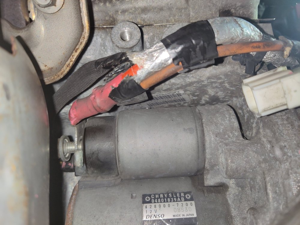
The same. 3.6 engine starter red cable goes to the under hood fuse box battery terminal stud. The dirty orange wire is the fusible link for the alternator on the cable that goes to it.
-
C0021-02 Brake Booster - General Signal Failure
Dean H replied to DodgeBruhBoy's topic in Brake, Chassis & Suspension
Both relearns using a capable scan tool. -
C0021-02 Brake Booster - General Signal Failure
Dean H replied to DodgeBruhBoy's topic in Brake, Chassis & Suspension
Try the the throttle body relearn function. -
Battery Died, now it won't start?
Dean H replied to DodgeBruhBoy's topic in Electrical, Battery & Charging
So what resolved this issue? -
Battery Died, now it won't start?
Dean H replied to DodgeBruhBoy's topic in Electrical, Battery & Charging
The P0016 code needs to fixed first. The PCM is seeing the camshaft position out of phase with the crankshaft position. The PCM needs the timing to be correct to determine spark and fuel for the engine. Causes: Sensors and wiring Mechanical timing chain and camshaft VVT solenoids. Using a capable scan tool, the cam-crank relearn must be done. It's done engine off. Using the scan tool you can check if the cam crank sensors are in sync. The scanner may point you to a problem with a sensor. The cam crank sensors must be in sync. After that if the code is still present and the engine doesn't start. You will be looking into the mechanical aspect. Timing chain and cam related stuff. -
Battery Died, now it won't start?
Dean H replied to DodgeBruhBoy's topic in Electrical, Battery & Charging
There is a cam crank relearn procedure on a bidirectional scan tool. That has to be done to get the cam and crank sensors in sync. -
Electrical System FYI - ground system
Dean H replied to Dean H's topic in Electrical, Battery & Charging
I was unable to jack my vehicle off the ground. So, I cut through the seal from the inside. -
Electrical System FYI - ground system
Dean H replied to Dean H's topic in Electrical, Battery & Charging
Read this thread too. https://www.dodgejourneyforum.com/topic/18115-electrical-system-fyi-cables/ -
Electrical System FYI - ground system
Dean H replied to Dean H's topic in Electrical, Battery & Charging
To answer your questions regarding the grounds on the driver's side strut tower. On the large stud is a 2 gauge cable to battery. 2 gauge to the engine block ground stud. On the middle stud is 4 gauge ground to the engine block somewhere. I did that first before upgrading everything. Just left it on.
-
Electrical System FYI - ground system
Dean H replied to Dean H's topic in Electrical, Battery & Charging
Hello, First, when I did this work, I had too much bulk cable and time and got a little crazy. First check out my thread on the battery below. https://www.dodgejourneyforum.com/topic/18210-electrical-system-fyi-battery/ A realistic ground upgrade would be this. Passenger motor Mount to strut tower ground studs. This is a weak ground. - 4 or 6 gauge cable to replace small ground wire. - mending bar or wire stud to stud. Driver's side strut tower battery ground stud. - 2 gauge cable from this stud to the engine block stud. Next to the electric vacuum pump. You need ⅜" size lugs on both ends of the cable. -Running a cable inside to the factory stud on the passenger side kick panel. To the right of the glove box. -A cable to the bolt to the left of the cabin air filter. That is all you need. I wish, I knew the length of cable to the interior. I don't. -
Installing a battery disconnect switch on a dodge journey
Dean H replied to Cornel's topic in Accessories, Modifications
Underhood battery connections below. Negative terminal large stud on the strut tower. Positive cable connection on TIPM under red cover.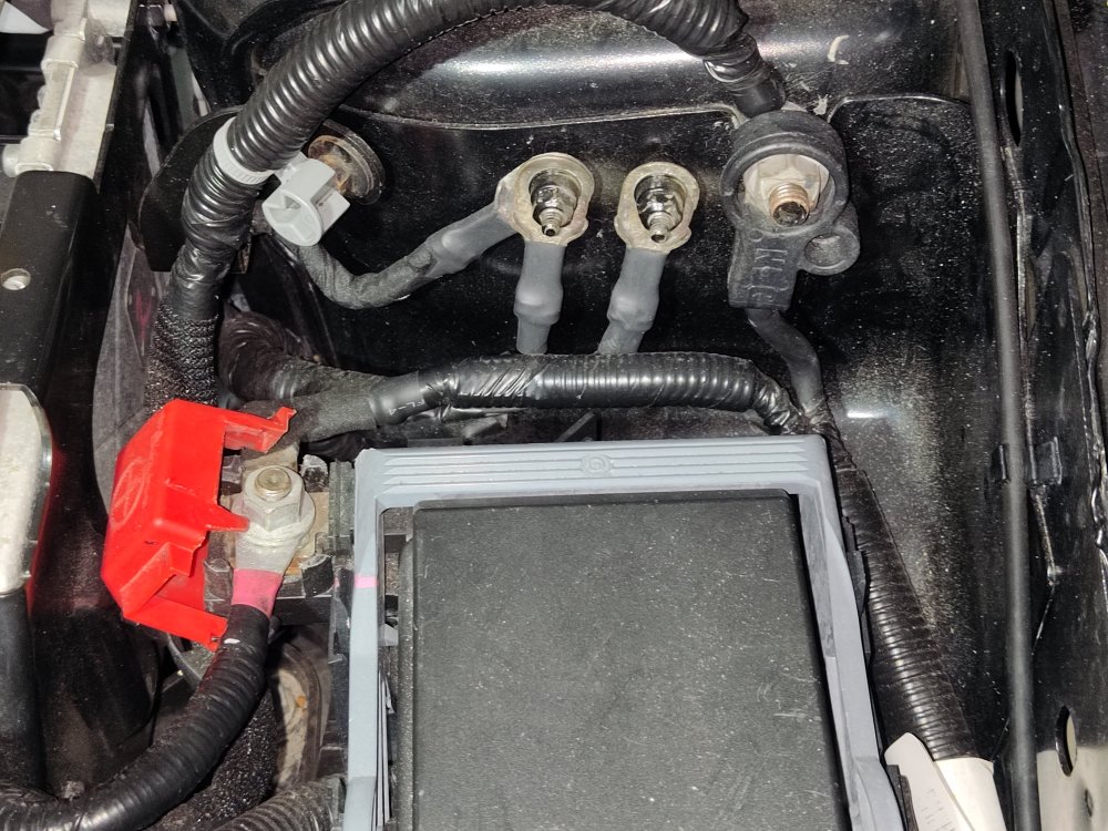
- 1 reply
-
- 1
-

-
2015 Dodge journey se 2.4L not starting at all
Dean H replied to Brook's topic in Maintenance & D.Y.I.
Dodge journey service information. P0600 serial communication link. -PCM detects internal failure. -Check PCM connectors and grounds. Clear codes if it returns, Replace PCM. This is the battery negative ground on the right large cable. The PCM grounds through one of the 2 small studs. Check these and clean.
-
2015 Dodge journey se 2.4L not starting at all
Dean H replied to Brook's topic in Maintenance & D.Y.I.
The electrical system is a major weak point on the Journey. Read these 2 threads linked below, regarding the Journey's electrical system. Read through the entire thread carefully. You need to go over these basic checks. Concerning the low voltage issue. I will post information on your code, when I get a chance. Battery https://www.dodgejourneyforum.com/topic/18210-electrical-system-fyi-battery/ Ground system https://www.dodgejourneyforum.com/topic/18374-electrical-system-fyi-ground-system/ -
After the previous steps have been done. Using a bi-directional scanner. Check if it can communicate with the abs module. Using a Dodge wiring diagram. Next, would be to check the ABS module connector for damage and any broken wires. The CAN BUS communication lines are 2 small wires twisted together. The ABS MODULE itself could be shorted out internally. The ABS module is hidden up underneath the passenger side cowl in the engine bay.

-
#1) Battery- tested healthy. #2) Battery cables and ground connections cleaned. #3) Check fuses for ABS in the Underhood fuse box. TIPM. Inside the lid shows the fuse diagram. F141 40 amp F173 25 amp F156 10 amp #4) ABS module grounds. There are 2 ground wires. Passenger strut tower 2 ground studs. Clean and check for broken wires.

-
U0121-00- LOST COMMUNICATION WITH ANTI-LOCK BRAKE SYSTEM (ABS) CONTROL MODULE ا Set Conditions: The Body Control Module (BCM) does not receive any CAN Bus messages from the Anti-lock Brake System (ABS). Causes- ANTI-LOCK BRAKE SYSTEM MODULE (ABS) POWERS AND GROUNDS ANTI-LOCK BRAKE SYSTEM MODULE (ABS) CAN C BUS (+) CIRCUIT OPEN CAN C BUS (-) CIRCUIT OPEN
-
Get the codes read by a shop with bi-directional scanner.
-
Blank Screen
Dean H replied to The Salmon's topic in Audio, Infotainment Navigation, MyGig, UConnect, etc.
I covered the battery and grounds in the threads linked below. Read through the entire thread and all of the posts. https://www.dodgejourneyforum.com/topic/18210-electrical-system-fyi-battery/ https://www.dodgejourneyforum.com/topic/18374-electrical-system-fyi-ground-system/ -
You need to get it read for codes. This will give us something to work with. Start with the battery, cables and ground cables. Go here for all the details - https://www.dodgejourneyforum.com/topic/18210-electrical-system-fyi-battery/ https://www.dodgejourneyforum.com/topic/18374-electrical-system-fyi-ground-system/
-
Electrical System FYI - ground system
Dean H replied to Dean H's topic in Electrical, Battery & Charging
If your battery CCA is up to spec. I would go through every battery cable and ground connection. Clean, seated and tight. Scan for codes. -
Here is the charging system thread. https://www.dodgejourneyforum.com/topic/18296-charging-system-101-with-diagrams/
-
CODE P0622 Code sets- When the PCM attempts to regulate the alternator field with no result. The PCM constantly regulates the alternator output. Based several different factors. My 3.6. 16 DJ while running, consistently stays between 13.5V and 14.3V. I believe that when the PCM is unable to control the alternator. It goes full field, maximum output . Which is why your getting output readings of 14.5 to 14.7 volts. Using a bi-directional scan tool you can check the PCM pulse width modulate signal percentage. It will be a fluctuating % number. Check that and see what the scan tool shows the PWM as. Possible Causes for the code. ALTERNATOR FIELD CONTROL CIRCUIT SHORTED TO BATTERY VOLTAGE ALTERNATOR FIELD CONTROL CIRCUIT OPEN/HIGH RESISTANCE ALTERNATOR FIELD CONTROL CIRCUIT SHORTED TO GROUND POOR ENGINE BLOCK OR ALTERNATOR CASE GROUND ALTERNATOR POWERTRAIN CONTROL MODULE (PCM) The alternator has a plug with 2 wires. One is from the PCM alternator field control wire. The other is a alternator sense wire. This wire tells the PCM it's changes are being made.
-
Code P0706 Simply put the the PCM doesn't know what gear the transmission is in. Using a bi-directional scanner you can check to see if the gear selected is read by the PCM on the scanner. Could be wiring to the transmission, range sensor or shift cable. P0688 ASD RELAY Code set - No voltage sensed at the PCM, when the ASD relay is energized. Check the TIPM, there is ASD fuses. Check for a ASD relay. On my 16 DJ, the ASD relay is inside the TIPM on the circuit board.
-
First Battery go here- https://www.dodgejourneyforum.com/topic/18210-electrical-system-fyi-battery/ The Ground system is a weak point on the Journey. https://www.dodgejourneyforum.com/topic/18374-electrical-system-fyi-ground-system/
-
Found this for your code: The Diesel Particulate Filter is an in-line canister filter located in the exhaust system between the engine and the muffler. This filter captures and stores soot and ash particles created by the diesel combustion process. The Diesel Particulate Filter is monitored by the Powertrain Control Module (PCM) with the Differential Pressure Sensor. This sensor measures the exhaust pressure before and after the particulate filter through tube connections directly on the exhaust pipe. Hoses run from the tubes to the Differential Pressure Sensor. As ash and soot accumulate in the filter, the exhaust pressure at the inlet side of the filter increases as compared to the pressure at the outlet side of the filter. Code sets- The Powertrain Control Module (PCM) detects incorrect exhaust flow through the particulate filter during certain engine operating conditions. Possible Causes DAMAGED EXHAUST SYSTEM LEAKING EXHAUST SYSTEM HIGH RESISTANCE IN EXHAUST DIFFERENTIAL PRESSURE SENSOR CIRCUITS HOSE/TUBE CONNECTIONS TO THE EXHAUST DIFFERENTIAL PRESSURE SENSOR Exhaust Differential pressure sensor Diesel particulate filter


