Journey_SeXT
-
Posts
813 -
Joined
-
Last visited
-
Days Won
39
Content Type
Profiles
Forums
Gallery
Everything posted by Journey_SeXT
-
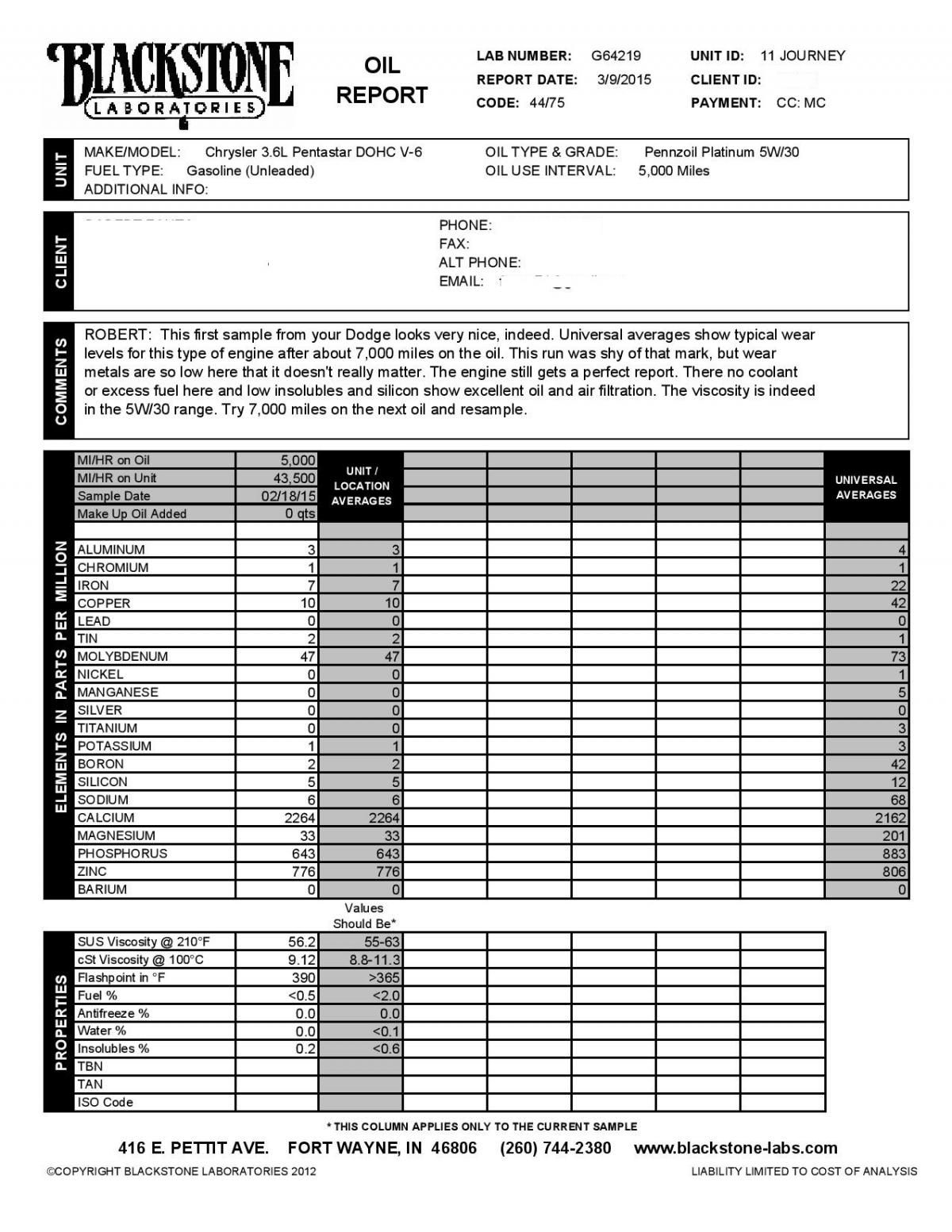
Calcium is a detergent in the engine oil. Molekule "BITOG" oil guru probably explains it best here: Calcium is mainly a detergent and magnesium at one time was used in dispersants but its use has declined since magnesium leaves ash deposits. Newer ashless dispersants are now used to disperse sludge molecules and soot. Calcium compounds are "multifunctional" additives since they not only lift deposits, but also serves as a friction modifier and tbn booster.
-
TBN gives you the amount of life left in your oil....this is excellent for those trying to max out their oil change interval which I would never do but for those who do the 10,000 mile plus oil change they might want to see if the oil can handle it or not.
-
I was at 43,500 miles (70,000 km's). The cost is $25.00 and if you want you can get the TBN for $10.00 extra. I did it just to know for sure that everything is okay and if I'm okay to extend my intervals which I can. You can check it out here: http://www.blackstone-labs.com/
-
Fluid And Filter Service FLUID AND FILTER SERVICE FLUID/FILTER SERVICE (RECOMMENDED) NOTE Refer to the maintenance schedules in LUBRICATION and MAINTENANCE, or the vehicle owner's manual, for the recommended maintenance (fluid/filter change) intervals for this transaxle. NOTE Only fluids of the type labeled MOPAR® ATF+4 should be used. A filter change should be made at the time of the transmission oil change. The magnet (on the inside of the oil pan) should also be cleaned with a clean, dry cloth. NOTE If the transaxle is disassembled for any reason, the fluid and filter should be changed. Raise vehicle on a hoist. Refer to LUBRICATION and MAINTENANCE for proper procedures. Place a drain container with a large opening, under transaxle oil pan. Loosen pan bolts and tap the pan at one corner to break it loose allowing fluid to drain, then remove the oil pan. Remove nuts at the oil filter. Install a new filter and nuts, tighten to 5 N·m (40 in. lbs.). Install the fluid filter oil pan, use a bead of MOPAR® ATF RTV (MS-GF41). Clean the oil pan and magnet. Reinstall pan using new MOPAR® Silicone Adhesive sealant. Tighten oil pan bolts to 12 N·m (105 in. lbs.). Pour four Quarts of MOPAR® ATF+4 through the dipstick opening. Start engine and allow to idle for at least one minute. Then, with parking and service brakes applied, move selector lever momentarily to each position, ending in the park or neutral position. Check the transaxle fluid level and add an appropriate amount to bring the transaxle fluid level to 3 mm (1/8 in.) below the lowest mark on the dipstick. Recheck the fluid level after the transaxle has reached normal operating temperature 82° C (180°F). Refer to Fluid Level and Condition Check for the proper fluid fill Fluid Level And Condition Check FLUID LEVEL AND CONDITION CHECK FLUID LEVEL CHECK USING THE SCAN TOOL TEMP CHART Click to Enlarge Verify that the vehicle is parked on a level surface. Remove the dipstick tube cap. WARNING There is a risk of accident from vehicle moving when the engine is running. Secure vehicle to prevent it from moving. There is a risk of injury from contusions and burns if you insert your hands into the engine when it is running. Do not touch hot or rotating parts. Wear properly fitted work clothes. Actuate the service brake. Start engine and let it run at idle speed in selector lever position "P". Shift through the transmission modes several times with the vehicle stationary and the engine idling. NOTE When inserting dipstick special tool Dipstick, excess insertion force may cause the dipstick to slip past the stop on the bracket in the transmission oil pan. An approximate distance that the dipstick sould be inserted into the fill tube is 424 mm (16.69 in.). Warm up the transmission, wait at least 2 minutes and check the oil level with the engine running. Push the Oil Dipstick Dipstick into transmission fill tube until the dipstick tip contacts the oil pan and pull out again, read off oil level, repeat if necessary. NOTE The dipstick will protrude from the fill tube when installed. Check transmission oil temperature using the appropriate scan tool. The transmission Oil Dipstick Dipstick has indicator marks every 10 mm. Determine the height of the oil level on the dipstick and using the height, the Transmission Fluid Temperature (TFT) as viewed with the scan too, and the Transmission Fluid Graph, determine if the transmission oil level is correct. Add or remove oil as necessary and recheck the oil level. Once the oil level is correct, install the dipstick tube cap. FLUID CONDITION Along with fluid level, it is important to check the condition of the fluid. When the fluid smells burned, and is contaminated with metal or friction material particles, a complete transaxle recondition is probably required. Be sure to examine the fluid on the dipstick closely. If there is any doubt about its condition, drain out a sample for a double check. MOPAR® ATF+4 (Automatic Transmission Fluid) when new is red in color. The ATF is dyed red so it can be identified from other fluids used in the vehicle such as engine oil or antifreeze. The red color is not permanent and is not an indicator of fluid condition. As the vehicle is driven, the ATF will begin to look darker in color and may eventually become brown. This is normal. ATF+4
-
I'm still hoping for a Youtube how-to on this but I think I'll have it done by the dealer.....seems like a real pain to do.
-
Hi All, Thought I would share my oil analysis sheet after a 5,000 mile / 8,000 km OCI with Pennzoil Platinum 5w-30 and a Bosch Premium Filter after a very cold winter. I was surprised at the results and hope this will eliminate any fears for anyone who would like to go a little longer with their OCI's. I think I will go 10,000 km's / 6,000 mile on the next change with Valvoline Synpower 5w30. Dodge really did a good job with these Pentastar engines.
-
 If I ever do this job I'll post the step by step pics but I'm still a whiles away from replacing them...I'm looking forward to do this job as I'm sure the cost savings and challenge will be rewarding.
 -
Let me know if there is anything else you need instructions on.
-
Upper UPPER NOTE Prior to installing the upper intake manifold, verify that the four fuel rail bolts were not inadvertently loosened. The bolts must tightened in the sequence shown to 7 N·m (62 in. lbs.) (Refer to Fuel System/Fuel Delivery/RAIL, Fuel - Installation)(Refer To List 1). Clean and inspect the sealing surfaces. Install new upper to lower intake manifold seals (1). NOTE Make sure the fuel injectors and wiring harnesses are in the correct position so that they don't interfere with the upper intake manifold installation. If removed, install the insulator (2) to the two alignment posts (3) on top of the LH cylinder head cover. Lift and hold the seven upper intake attaching bolts (1) clear of the mating surface. Back the bolts out slightly or if required, use an elastic band to hold the bolts clear of the mating surface. Position the upper intake manifold (1) onto the lower intake manifold so that the two locating posts (2) on the upper intake manifold align with corresponding holes (3) in the lower intake manifold. Install the seven upper intake manifold attaching bolts. Tighten the bolts in the sequence shown to 10 N·m (89 in. lbs.). Install two nuts (1) to the upper intake manifold support bracket (5). Tighten the nuts (1) to 10 N·m (89 in. lbs.) and tighten the studbolt (2) to 20 N·m (177 in. lbs.) Engage the wire harness retainer (3) to the studbolt (2). Engage the wire harness retainer (4) to the upper intake manifold support bracket (5). Install two upper intake manifold support brackets (2) with two studbolts (3) and two nuts (1). Tighten the studbolts (3) to 20 N·m (177 in. lbs.) and tighten the nuts (1) to 10 N·m (89 in. lbs.). Install the nut (2) to the support bracket of the heater core return tube (1) and tighten to 12 N·m (106 in. lbs.). Connect the following hoses to the upper intake manifold: Positive Crankcase Ventilation (PCV) (3) vapor purge (6) brake booster (2) Connect the electrical connectors to the Manifold Absolute Pressure (MAP) sensor (1) and the Electronic Throttle Control (ETC) (7). Secure the ETC harness to the clip (7) on the throttle body and engage the wire harness retainers (4 and 5) to the upper intake manifold near the MAP sensor. Install the resonator (1) (Refer to Engine/Air Intake System/RESONATOR, Air Cleaner - Installation). Connect the negative battery cable and tighten nut to 5 N·m (45 in. lbs.). Start and run the engine until it reaches normal operating temperature. Install the engine cover (1).
-
3.6L 3.6L Check and adjust the spark plug gap with a gap gauging tool (1) (Refer to Electrical/8I - Ignition Control - Specifications) CAUTION Special care should be taken when installing spark plugs into the cylinder head spark plug wells. Be sure the plugs do not drop into the plug wells as electrodes can be damaged. CAUTION The spark plug tubes (1) are a thin wall design. Avoid damaging the spark plug tubes. Damage to the spark plug tube can result in oil leaks. Start the spark plug into the cylinder head by hand to avoid cross threading. CAUTION Spark plug torque is critical and must not exceed the specified value. Overtightening stretches the spark plug shell reducing its heat transfer capability resulting in possible catastrophic engine failure. Tighten the spark plugs to 18 N·m (13 ft. lbs.). NOTE The LH ignition coils are shown, the RH ignition coils are similar.
-
3.6L 3.6L NOTE The LH ignition coils are shown, the RH ignition coils are similar. Remove the ignition coil (2) (Refer to Electrical/8I - Ignition Control/COIL, Ignition - Removal). Prior to removing the spark plug, spray compressed air into the cylinder head opening. This will help prevent foreign material from entering the combustion chamber. CAUTION The spark plug tubes (1) are a thin wall design. Avoid damaging the spark plug tubes. Damage to the spark plug tube can result in oil leaks. Remove the spark plug from the cylinder head using a quality thin wall socket with a rubber or foam insert.
-
Upper UPPER Disconnect and isolate the negative battery cable. Remove the engine cover (1). Remove the resonator (1) (Refer to Engine/Air Intake System/RESONATOR, Air Cleaner - Removal). Disconnect the electrical connectors from the Manifold Absolute Pressure (MAP) sensor (1) and the Electronic Throttle Control (ETC) (7). Disengage the ETC harness from the clip (8) on the throttle body. Disengage the wire harness retainers (4 and 5) from the upper intake manifold near the MAP sensor and reposition the wire harness. Disconnect the following hoses from the upper intake manifold: Positive Crankcase Ventilation (PCV) (3) vapor purge (6) brake booster (2) Disengage the wire harness retainer (4) from the upper intake manifold support bracket (5). Disengage the wire harness retainer (3) from the studbolt (2). Remove two nuts (1), loosen the studbolt (2) and reposition the upper intake manifold support bracket (5). Remove the nut (2) from the support bracket of the heater core return tube (1). Remove two nuts (1), loosen two studbolts (3) and reposition the two upper intake manifold support brackets (2). NOTE The upper intake manifold attaching bolts are captured in the upper intake manifold. Once loosened, the bolts will have to be lifted out of the lower intake manifold and held while removing the upper intake manifold. NOTE Exercise care not to inadvertently loosen the two fuel rail attachment bolts that are in close proximity of the upper intake manifold attaching bolts. Remove seven manifold attaching bolts (1) and remove the upper intake manifold (2). Remove and discard the six upper to lower intake manifold seals (1). Cover the open intake ports to prevent debris from entering the engine.
-
Yeah, just don't reset it after a fill up and before a long line up at the car wash. My Accent resets itself automatically after every fill up and the wait at the wash brought the reading to 99.9L/100 km's.
-
Lovin' my 2011 SXT. Great ride, decent fuel mileage and no problems as of yet (knock on wood). Would I get another...you betcha!
-
3.6L 3.6L Click to Enlarge Position new gaskets onto the catalytic converter flanges. Position the cross-under pipe (1) into its position between the catalytic converters. Install the front flange mounting nuts (4). Tighten nuts to 28 Nm (250 in.-lbs.). Install the rear flange bolts (5). Tighten bolts to 30 N.m (22 ft. lbs.). Install the cross-under support (2) bolts. Tighten nuts to 28 Nm (250 in.-lbs.). Install the muffler/resonator pipe (2) onto the cross-under pipe (4). Do not tighten the pipe clamp. Install the half shaft (Refer to Differential and Driveline/Half Shaft - Installation)(Refer To List 1). Install the front pipe grommet (4). Check for clearance of the exhaust to body. Tighten the muffler/resonator pipe clamp (3) to 55 N·m (40 ft. lbs.).
-
3.6L 3.6L Check condition of all pulleys. CAUTION When installing the serpentine accessory drive belt, the belt MUST be routed correctly. If not, the engine may overheat due to the water pump rotating in the wrong direction. Install new belt (7). Route the belt around all pulleys except the idler pulley (2). Rotate the tensioner arm (8) until it contacts its stop position. Route the belt (7) around the idler (2) and slowly let the tensioner (8) rotate into the belt. Make sure the belt (7) is seated onto all pulleys. With the drive belt installed, inspect the belt wear indicator. The gap between the tang and the housing stop ( measurement A ) must not exceed 24 mm (.94 inches). Install the inner splash shield. Install the wheel.
-
3.6L Engine 3.6L ENGINE NOTE Before installing power steering pressure hose on power steering pump, replace O-ring on end of power steering pressure hose. Lubricate O-ring using clean power steering fluid. Install power steering pump (1) onto its mounting bracket. Install three power steering pump mounting bolts through pulley (not shown in figure). Tighten pump mounting bolts to 30 N·m (22 ft. lbs.). Install power steering pump pressure fitting (2) and tighten to 32 N·m (24 ft. lbs.). Slide fluid supply hose onto pump (3) fitting and install clamp (1) securing it in place. Install heat shield (1) and secure with 3 mounting bolts (2). Tighten bolts to 25 N·m (18 ft. lbs.) Install exhaust pipe (Refer to Exhaust System/PIPE, Exhaust Crossunder/Installation) . Lower vehicle. Install accessory drive belt (Refer to Cooling/Accessory Drive/BELT, Serpentine - Installation) Connect negative (-) battery cable on negative battery post.
-
3.6L 3.6L Click to Enlarge Disconnect the negative battery. Hoist the vehicle. If equipped, remove lower engine shield. Remove the two cross-under support (2) bolts. Remove the front flange nuts (4) from the flange studs. Remove the rear flange bolts (5). NOTE To help aid in the cross-under pipe removal. The front exhaust pipe grommet needs to be removed. Remove the front muffler/resonator pipe grommet (4). Using a jack or suitable stand. Position the stand under the muffler piping to help support and aid in removal from the cross-under pipe. NOTE Removal of the half shaft will gain access to the exhaust pipe and aid in its separation due to tight tolerances. Remove the half shaft assembly on the passenger side (Refer to Differential and Driveline/Half Shaft - Removal)(Refer To List 1). Loosen clamp (5) and remove the muffler/resonator pipe (2) from cross-under pipe (4). Remove the cross-under pipe (4) from vehicle and discard gaskets.
-
3.6L 3.6L CAUTION Do not let tensioner arm snap back to the freearm position, severe damage may occur to the tensioner. Disconnect negative battery cable from battery. Raise vehicle. Remove right front wheel.
-
3.6L Engine 3.6L ENGINE Remove negative (-) battery cable from battery and isolate cable. Remove cap from power steering fluid reservoir. Using a siphon pump, remove as much power steering fluid as possible from power steering fluid reservoir. Remove accessory drive belt (Refer to Cooling/Accessory Drive/BELT, Serpentine - Removal) Raise and support vehicle (Refer to Vehicle Quick Reference/Hoisting - Standard Procedure). Remove exhaust pipe (Refer to Exhaust System/PIPE, Exhaust Crossunder/Removal). Remove 3 heat shield mounting bolts (2). Remove heat shield (1) from vehicle. Remove supply hose clamp (1) and remove supply hose from power steering pump fitting. Remove power steering pump pressure hose fitting (2). Remove three pump mounting bolts through pump pulley (not shown in figure).
-
Removal REMOVAL LOWER FASCIA Remove fasteners (5) to lower closeout. CLOSEOUT- FRONT LOWER FASCIA
-
Removal REMOVAL UPPER PUSHPINS Release hood latch and open hood. Remove the pushpins for the fascia (2) at the radiator support. POP RIVETS Hoist and support vehicle on safety stands. (Refer to Vehicle Quick Reference/Hoisting - Standard Procedure), for proper hoisting and jacking procedures. Remove the pop rivets (2) at the wheel well opening. TABS/BRACKET Remove the torx® screw (3) at the wheel well housing. Separate the fascia tabs (2) at the bracket (1). LOWER PUSHPINS Remove the pushpins (1) for the fascia (2) at the lower closeout panel. SLIDE MOUNT Slide the fascia (2) out from the mounting tab (1) under the headlamp. Disengage fog lamp wire connector and side marker connector from body harness, if equipped. Disengage the ambient temp sensor wire connector, if equipped.
-
Reviving this 4 year old thread but yes it is ridiculously easy to change oil on the DJ. If I were to install a Fumoto drain valve I think my 8 yr. old son could do the oil change on his own.
-
You're under warranty just take it to the dealer and let us know what they find.
-
The manual doesn't make any mention of an early first oil change but it is your vehicle and you can change the oil whenever you'd like. Just do not pass whatever the maximum limit is stated in your owners manual and you'll be fine. Personally, I am not a big fan of extended oil changes and replace it at every 4 - 5,000 miles with my first one was done at 3,000 miles. Congrats on the new Journey!