

Ray_Richter
-
Posts
2 -
Joined
-
Last visited
-
Days Won
2
About Ray_Richter
-
 NavalLacrosse reacted to a post in a topic:
Not starting when cold out - Solved
NavalLacrosse reacted to a post in a topic:
Not starting when cold out - Solved
-
 OhareFred reacted to a post in a topic:
Not starting when cold out - Solved
OhareFred reacted to a post in a topic:
Not starting when cold out - Solved
-
 larryl reacted to a post in a topic:
Not starting when cold out - Solved
larryl reacted to a post in a topic:
Not starting when cold out - Solved
-
Not starting when cold out - Solved
Ray_Richter replied to Ray_Richter's topic in Electrical, Battery & Charging
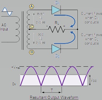
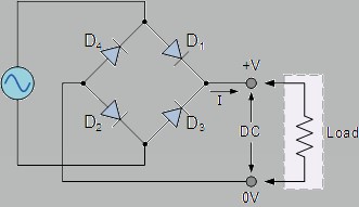
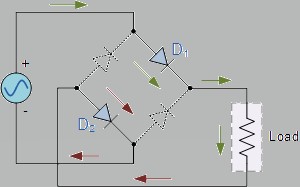
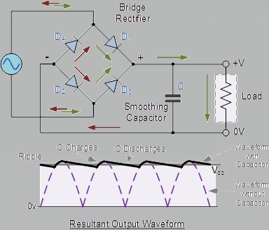
I guess I should explain better. All chargers/boosters that you plug into a wall outlet uses the AC 120v-240v depending where your live (which country), here in North America we use 120 vac. We run this AC through a step down transformer to about 15 VAC. Now when you step down the voltage you increase the available current by the same ratio. So if you have an AC outlet with 120vac and a 15 amp breaker and you step down the voltage by 10x the available current will be 150 amps AC. Now a battery can act just like a diode which only allows current to flow in 1 direction, mind it's not a very good diode. To get DC voltage and current we have to run that AC voltage & amperage through diodes to get DC voltage and current. Problem is that makers of chargers & boosters usually go cheap on the electronics. To keep costs down they will either use a half-wave rectifier or a full-wave rectifier setup but, not a full-wave bridge rectifier, which is closer to real DC power. A Full-wave bridge rectifier with a smoothing capacitor will give DC power that is very close to true DC power that computers like. But there are problems with these setups. To begin the transformer outputs are usually 16 VAC because each diode will drop about 1.5 volts each, so going through 1 diode (half-wave rectification) the output voltage will drop to 14.5 VAC, going through 2 (full-wave rectification) brings it down to 13 volts pulsed DC. But going through a full-wave bridge rectification still gives you 13 volts DC with ripples, add the smoothing capacitor and you will bring the voltage up to 13.5-14.0 DC. But each step up in the process costs money. Usually when you switch a charger/booster to boost it usually bypasses the rectifiers and gives the full stepped down AC for starting. Remember batteries can act like a poor diode and that's what the manufacturers are hoping will work. A 200 amp bridge rectifier costs between $75-$150 dollars, ouch. A 10 amp bridge rectifier costs between $1.23-$3.04. A 25 amp bridge rectifier costs between $1.15- $19.94. A 50 amp bridge rectifier costs between $3.68-$67.90. Now this is just for the full-wave bridge rectifier, that doesn't include the transformer or the rest of the parts. Also electronic equipment is usually marked up 1,200%. Half-Wave rectifier - notice that the output is not even half DC. Full-Wave rectifier - RL is any load, but still output is still not DC and regulators will see the average of the voltage out. Full-Wave Bridge rectifier - output is close to being DC but with some major AC ripple. Negative Half-cycle Positive Half-cycle Full-wave Rectifier with Smoothing Capacitor - about as close to real DC your going to get. All computer electronics used in automotive are either 5vdc or 3.3vdc. The proper way to lower the 12.5-15vdc that the car uses is to reduce the voltage down from the 12.5 - 15vdc to 6-7v then to 5vdc then to 3.3vdc. This is done to prevent overheating the regulators. Now I can and do use regulators that check the incoming power to make sure that it is at the proper level say 12vdc. But since most battery chargers are half-wave, the voltage regulator will not see 12vdc it will see about 7vdc from the charger/booster because 7vdc is about the equivalent of 12vac. So the regulator will not turn on, if it does not turn on the car will not start. The computer gets a no-good power indication and will not let the car start. This is done to prevent wonky behavior and relay chatter or so the design engineer thought. The thing is that 12vdc relays usually will pickup at 9vdc so there is no reason to have a regulator that cuts out at below 12vdc. Now batteries at -0F or -18C only have half the amperage than they do at room temperature. At this temperature their voltage usually goes down to =<11.5vdc and this is not enough for the voltage regulator to turn. I should also mention that there is usually more than one computer and more than 1 regulator which is why you will hear a click of a relay but no engine cranking. So how to fix this problem; 1. FCA/Chrysler/Dodge should do a recall and replace the offending computer either the BCM or EMC and they can replace the regulator on the computer board with a proper one that's not just meant for California. 2. Is to use a battery maintainer or a small trickle charger to keep the battery voltage up above 12 volts. On my sisters Journey I used 12 vdc power supply (actually 15vdc) meant for powering up all kinds of devices. The other night the temperature went down to -38C with a wind-chill of -50C and her Journey started with no problems in the morning, a true first for that vehicle. External Links: https://www.electronics-tutorials.ws/diode/diode_5.html https://www.electronics-tutorials.ws/diode/diode_6.html I hope this all helps. Ray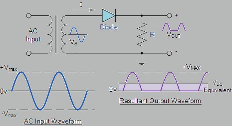
-
 larryl reacted to a post in a topic:
Not starting when cold out - Solved
larryl reacted to a post in a topic:
Not starting when cold out - Solved
-
How I fixed my sisters non stating Journey on cold days. First I want to say that my sister bought her 2010 Journey used in the summer of 2015, it came with a brand new battery. In the first winter the car would not start it would just click, headlights would be nice and bright. Now I was a mechanic when I was young. I joined the military and became a RADAR technician, learning all kinds of electronics. Today I am a Computer Analyst/Programmer and I still make electronic devices. So after my sister replaced 3 batteries in 5 years, the lockout solenoid, starter, ignition switch, and neutral safety switch I new there had to be something else wrong. Anyway the only thing I replaced was her first battery, she did have the rest of the work done at a local garage and a local dealer, neither could solve the problem. Then last winter she could not start her car when leaving work and she called me. So I didn't take my jumper cables because they were broken so I took my battery charger/booster with me. I tried to use my booster but, no luck. Then one of her employees came out with a booster that they use to boost the diesel trucks and that wouldn't work. Then someone came over with a small booster that used lithium batteries and can be also used as a power pack for cell phones and it worked. So I'm thinking, how the hell does this little battery pack start her Journey when a diesel truck booster wouldn't do it. Ok this is where my electronics training comes in. In all the times I boosted her Journey the battery voltage was at 11.5 - 11.8 volts. Now on a normal car/truck the vehicle will still start. I know my 95 Neon will start at 10.5. So I had a hunch. I use what is know as LDO voltage regulators. These regulators are used to protect electronic parts from things as brown-outs and low voltages that could damage them. Problem is these voltage regulators will not turn on if the incoming voltage is too low. Now most battery chargers and charger/boosters use what is know as half bridge or even a single diode to make what is supposed to be 12 vdc. Batteries need to charge at higher than 12 vdc usually between 12.6 and 14.3 vdc. So the battery charger/boosters that we used that late cold day did not put out 12 vdc but 15 vac and the voltage regulator in the on board computer did not think it was 12 vdc, which, is why that little battery booster with the batteries started the Journey and ours wouldn't. The guy barely touched the terminals and it started. The Fix: So this fall I put one of my battery maintainers on her Journey and told her too make sure she plugs in both her block heater and the battery maintainer. I connected the maintainer directly to the under hood terminals and not the battery. Now we are in our second cold snap here of where the temperature has gone below -28C/-18F with a wind-chill of -46C/-50.8F and her Journey started with the remote start no problem. She is very very grateful. So the way I see it, someone at Fiat/Chrysler screwed up on the design of the engine management computer and used a voltage regulator with a low voltage lockout that is set to high. Almost all of todays electronics work off 5vdc or even less, Sure the relays are listed at 12 vdc but they will pickup at 9 vdc I know I've tested them. The way I see it someone at Chrysler/Dodge owes a lot of people money for repairs and new computers. Ray Richter