Carter3Journey
-
Posts
18 -
Joined
-
Last visited
-
Days Won
2
Content Type
Profiles
Forums
Gallery
Everything posted by Carter3Journey
-
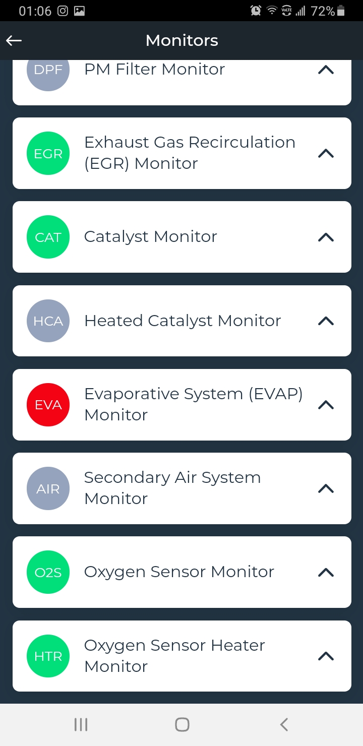
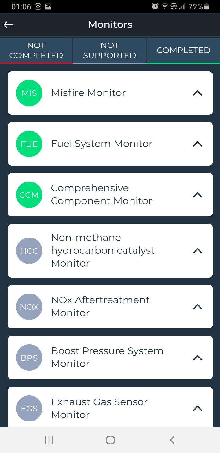
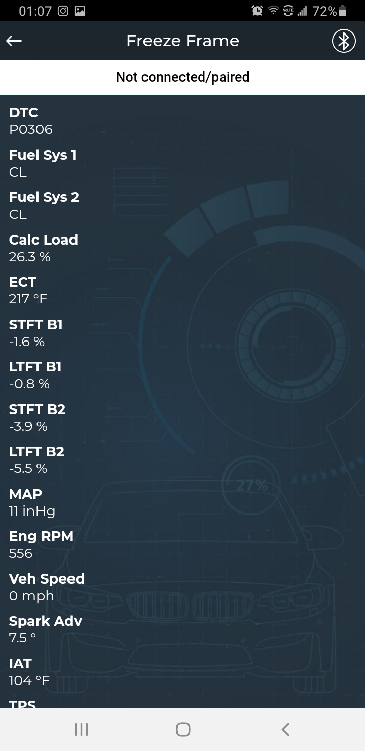
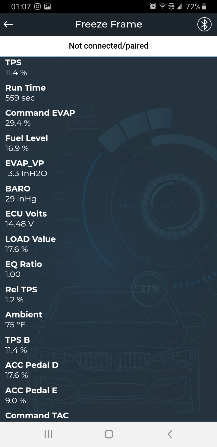
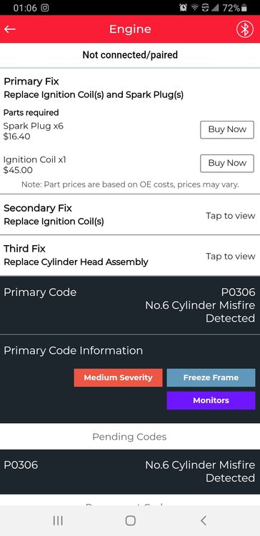
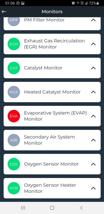
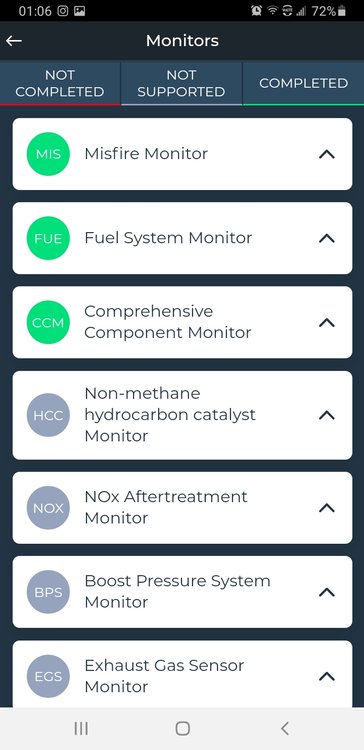
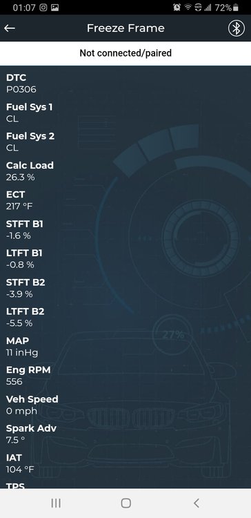
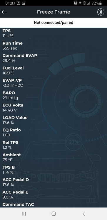
I have 2014 sxt awd miles 91928 with a cylinder 6 misfire been dealing with this for a few months I took picture of what my innova 5610 scan tool displays. Why does every other system monitor pass except Evap its red. I already replaced all spark plugs and cylinder 6 ignition coil. Pvc valve has been replace months back I checked for continuous clicking for the fuel injector for cylinder 6 and ran fuel injector cleaner in fuel tank. What Evap sensor can cause a misfire.Debating taking to dealer but next available appointment for diagnostic work was june 4.
-
I replaced the front two struts now my camber is off on both sides firestone stated over 260 buck to install cam bolt and alignment which I get alreafy for free but how many bolts do I need of a 14 mm with a range of 1.75 +/- for each strut
-
Rear lower control arm removal
Carter3Journey replied to detroitgrip's topic in Brake, Chassis & Suspension
Removal REMOVAL Raise and support the vehicle. (Refer to Vehicle Quick Reference/Hoisting - Standard Procedure) TIRE AND WHEEL MOUNTING Remove the wheel mounting nuts (3), then the tire and wheel assembly (1). REAR STABILIZER LINK If equipped, while holding the stabilizer bar link lower stud stationary, remove the nut (3) securing the link (2) to the lower control arm (4). SUPPORTING REAR SHOCK If equipped with load-leveling shocks, support the lower shock (1) with a jack (2) using just enough force to allow easy removal of the lower shock mounting bolt in the following step. Lower the jack following bolt removal. REAR LOWER SHOCK MOUNTING Remove the lower shock mounting nut (1) and bolt (4). REAR LOWER CONTROL ARM MOUNTING Remove the nut (2) and bolt (7) securing the lower control arm (3) to the knuckle (1). Remove the nut (4) and bolt (6) securing the lower control arm (3) to the rear crossmember (5). Remove the lower control arm (3). -
Front brake torque specs
Carter3Journey replied to YellowDuck's topic in Brake, Chassis & Suspension
Specs for front brakes are in pdf -
Front brake torque specs
Carter3Journey replied to YellowDuck's topic in Brake, Chassis & Suspension
Hope this helps Repair content for 2014 Dodge Journey(1).PDF -
62TE Transmission rear cover replacement
Carter3Journey replied to Tedybear315's topic in All Wheel Drive (AWD)
whats a part -
62TE Transmission rear cover replacement
Carter3Journey replied to Tedybear315's topic in All Wheel Drive (AWD)
Removal REMOVAL IAT SENSOR CONNECTOR Open the hood. Disconnect the negative battery cable. Disconnect the electrical connector (1) from the intake air temperature sensor (2), located at the air cleaner housing. AIR BOX Remove the hold down bolt (1) and hose clamp (2) at the air cleaner housing. Remove the air cleaner housing. SHIFT CABLE FROM MANUAL LEVER Disconnect the gearshift cable (1) from the transaxle manual valve lever (2). Remove the gearshift cable from the bracket. CKP SENSOR. Disconnect the electrical connector (2) from the crankshaft position sensor (3). Remove the hold down bolt (1) from the crankshaft position sensor (3). Remove the crankshaft position sensor. COOLER LINES AT TRANS Disconnect the transmission cooler lines from the transaxle using Trans Cooler Line Disconnect Disconnect, Transmission Cooler Line (Refer to Cooling/Transmission/TUBES AND HOSES, Transmission Oil Cooler - Standard Procedure). TRANS HARNESS CONNECTOR NOTE The transmission harness will be removed with the transaxle. Disconnect the transaxle electrical connector at the powertrain control module. UPPER TRANSMISSION BOLTS Remove the transaxle upper bellhousing-to-block bolts (3). REAR MOUNT TOP BOLTS Remove rear transaxle mount bracket bolts (1). GROUND CABLE AT FRONT MOUNT Remove the bolt (2) holding the ground cable (3) to the front mount bracket (1). Raise the vehicle on the hoist. Remove both halfshafts (Refer to Differential and Driveline/Half Shaft - Removal)(Refer To List 1). Remove the front and both side splash shields (Refer to Body/Exterior/SHIELD, Splash - Removal)(Refer To List 2). Remove the power takeoff unit, if equipped. CROSSMEMBER THROUGH BOLT Remove the mount through bolt (1). TRANS CROSSMEMBER Remove the transmission crossmember bolts (2). Remove the transmission crossmember. FRONT MOUNT BRACKET Remove the front mount bracket bolts (1). Remove the front mount bracket (2). Starter Motor and Shim Disconnect starter motor electrical connectors and remove the retaining bolts (3), starter motor (1) and shim (2). EXHAUST BRACKET AT INSPECTION CO Remove the bolts (3) from the exhaust bracket. Remove the cross under pipe (Refer to Exhaust System/PIPE, Exhaust Crossunder - Removal). Remove the bolts (2) to stand off bracket (4). Remove the bracket (4). DUST SHIELD Remove the torque converter dust shield bolt (3). Remove the torque converter dust shield (2). TORQUE CONVERTER BOLTS Remove the torque converter-to-driveplate bolts (1). Upon removing bolts, a tight-tolerance (slotted) bolt will be encountered. Mark this location (driveplate and converter) with paint for assembly reference. TORQUE CONVERTER BOLTS Install a transmission jack and support the engine. Secure transaxle to jack. NOTE The bolts on each side of the inspection opening were removed with the exhaust bracket. Remove the transaxle-to-engine lower bolts (2). LEFT MOUNT BOLTS Remove the left side transmission mount bolts (2) and remove the mount (1). Lower transaxle from engine compartment. Solenoid Connector at Transmission Disconnect the solenoid/pressure switch assembly connector (2). OUTPUT SPEED SENSORS Disconnect both output speed sensor connectors (1, 2). Disconnect the input speed sensor connector. Remove the harness from transaxle. Refer To List: List 1 03 - Differential and Driveline / Half Shaft, Front / Removal 03 - Differential and Driveline / Half Shaft, Rear / Removal List 2 23 - Body / Exterior / SHIELD, Splash, Front Wheelhouse / Removal 23 - Body / Exterior / SHIELD, Splash, Rear Wheelhouse / Removal -
Intake manifold hoses front of vehicle? 2.4
Carter3Journey replied to 2.4journey2013's topic in Engine & Transmission
Installation INSTALLATION INTAKE TORQUE SEQUENCE Clean all gasket surfaces. Replace intake manifold gasket. Install intake manifold, tighten bolts to 25 N·m (220 in. lbs.). Install the fuel rail assembly to intake manifold. Tighten bolts to 23 N·m (200 in. lbs.). COIL CONNECTOR Connect fuel injector electrical connectors (4). Inspect quick connect fittings for damage, replace if necessary (Refer to Fuel System/Fuel Delivery/FITTING, Quick Connect - Standard Procedure)(Refer To List 1). Connect fuel supply hose (3) to fuel rail assembly. Check connection by pulling on connector to make sure it is locked into position. JS GAS AIR BOX Install air cleaner housing (1). BATTERY CABLE Connect negative battery cable (1). Fill the cooling system (Refer to Cooling - Standard Procedure). Engine Cover Start engine and check for leaks. Install engine cover. Refer To List: List 1 14 - Fuel System / Fuel Delivery, Gas / FITTING, Quick Connect / Standard Procedure 14 - Fuel System / Fuel Delivery, Diesel / FITTING, Quick Connect / Standard Procedure -
Intake manifold hoses front of vehicle? 2.4
Carter3Journey replied to 2.4journey2013's topic in Engine & Transmission
Diagnosis And Testing - Intake Manifold Leaks DIAGNOSIS AND TESTING - INTAKE MANIFOLD LEAKS An intake manifold air leak is characterized by lower than normal manifold vacuum. Also, one or more cylinders may not be functioning. WARNING Use extreme caution when the engine is operating. Do not stand in a direct line with the fan. Do not put your hands near the pulleys, belts or the fan. Do not wear loose clothing. Start the engine. Spray a small stream of water (Spray Bottle) at the suspected leak area. If engine RPM'S change, the area of the suspected leak has been found. Repair as required. Injector Harness Click to enlarge -
Interior PDC Fuses INTERIOR PDC FUSES
-
C1581-00-Front/Rear Tire Pressure Sensor Location Undetermined C1581-00-FRONT/REAR TIRE PRESSURE SENSOR LOCATION UNDETERMINED For a complete wiring diagram, refer to the Wiring Information. NOTE Check for and remove any non-FCC compliant components before beginning this diagnostic procedure. Theory of Operation The vehicle Tire Pressure Monitoring (TPM) Sensor locate process occurs after the vehicle remains stationary for 20 minutes. The Tire Pressure Monitoring (TPM) Module will determine the Tire Pressure Monitoring (TPM) Sensor positions. The TPM Module measures the signal strength of each TPM sensor and determines if the are in the front or rear. When Monitored and Set Conditions When Monitored: This diagnostic runs continuously when the following conditions are met: Ignition on. System voltage between 10.0 and 16.0 volts. Vehicle TPM Sensor locate process. Set Conditions: New Tire Pressure Monitoring (TPM) Module has never attempted localization. Tire Pressure Monitoring (TPM) Module fails multiple vehicle TPM sensor locate processes if localization fails due to Front/Rear sensor failure. Default Actions: TPM Indicator lamp illuminated. Possible Causes NON-FCC COMPLIANT COMPONENTS TIRE PRESSURE MONITORING (TPM) MODULE HARNESS INCORRECT TIRE PRESSURE MONITORING (TPM) MODULE INSTALLATION TIRE PRESSURE MONITORING (TPM) MODULE Diagnostic Test CHECK FOR AN ACTIVE DTC NOTE The vehicle must remain stationary for 20 minutes before proceeding with this diagnostic procedure. Turn the ignition on. With the scan tool, read DTCs and record on the repair order. Test drive the vehicle at a speed greater than 24 km/h (15 mph) for 10 minutes in order to receive TPM Sensor data and allow for the system to update. With the scan tool, erase DTCs. With the scan tool, read TPM DTCs. Is the DTC active? Yes Go To >>> No Go To >>> TIRE PRESSURE MONITORING (TPM) MODULE INTERFERENCE NOTE Interference may occur if the TPM Module is installed incorrectly or the TPM harness is not fastened properly to the body. Turn the ignition off. Verify the following: Aftermarket devices are installed or in the vehicle. The TPM Module harness is damaged or is routed incorrectly. The TPM Module is installed incorrectly. Are there any of the above conditions present? Yes Repair as necessary. Perform the TPM VERIFICATION TEST. (Refer to DTC-Based Diagnostics/MODULE, Tire Pressure (TPM) - Standard Procedure). No Install a new Tire Pressure Monitoring (TPM) Module in accordance with the Service Information. (Refer to Tires and Wheels/Tire Pressure Monitoring/MODULE, Tire Pressure Monitoring (TPM) - Removal). Perform the TPM VERIFICATION TEST. (Refer to DTC-Based Diagnostics/MODULE, Tire Pressure (TPM) - Standard Procedure). INTERMITTENT TIRE PRESSURE MONITORING (TPM) SENSOR DTC The conditions necessary to set this DTC are not present at this time. Perform any Service Bulletins that may apply to this condition. With the scan tool, erase TPM DTCs. Test drive the vehicle for a minimum of 20 minutes with vehicle speed greater than 24 km/h (15 mph). With the scan tool, read TPM DTCs. Does the DTC remain active for this DTC? Yes Install a new Tire Pressure Monitoring (TPM) Module in accordance with the Service Information. (Refer to Tires and Wheels/Tire Pressure Monitoring/MODULE, Tire Pressure Monitoring (TPM) - Removal). Perform the TPM VERIFICATION TEST. (Refer to DTC-Based Diagnostics/MODULE, Tire Pressure (TPM) - Standard Procedure). No Test complete. Perform the TPM VERIFICATION TEST. (Refer to DTC-Based Diagnostics/MODULE, Tire Pressure (TPM) - Standard Procedure).
-
C1504-96-Tire Pressure Sensor 4 - Internal Component Failure C1504-96-TIRE PRESSURE SENSOR 4 - INTERNAL COMPONENT FAILURE For a complete wiring diagram, refer to the Wiring Information. NOTE Check for and remove any non-FCC compliant components, and verify that the tire pressures are correct, before beginning this diagnostic procedure. Theory of Operation The Tire Pressure Monitoring (TPM) Sensor actively monitors the air pressure, air temperature inside the tire, the direction of the tire rotation and the internal battery status. Each sensor has a unique ID code. The TPM Sensor transmits the data at regular intervals via an encoded signal to a receiver circuit located in the Tire Pressure Monitoring (TPM) Module. When Monitored and Set Conditions When Monitored: This diagnostic runs continuously when the following conditions are met: Ignition on. System voltage between 10.0 and 16.0 volts. Vehicle speed above 24 km/h (15 mph). Set Conditions: Tire Pressure Monitoring (TPM) Module receives RF signal error if data is not received or cannot be accurately decoded for a maximum of 20 minutes when the vehicle speed is above 24 km/h (15 mph). Tire Pressure Monitoring (TPM) Module receives internal sensor hardware error. Tire Pressure Monitoring (TPM) Module senses error in the shock sensor, pressure sensor, or temperature sensor. Default Actions: Tire Pressure Monitoring (TPM) Module Lamp will flash on and off for 75 seconds then remain on solid. Possible Causes NON-FCC COMPLIANT COMPONENTS AFTERMARKET TIRES/WHEELS INTERMITTENT TIRE PRESSURE MONITORING (TPM) SENSOR INTERNAL DTC TIRE PRESSURE MONITORING (TPM) SENSOR TIRE PRESSURE MONITORING (TPM) MODULE Diagnostic Test CHECK FOR AN ACTIVE DTC NOTE Before beginning diagnostic procedure, verify that tire pressures are correct. Turn the ignition on. With the scan tool, read DTCs and record on the repair order. Test drive the vehicle at a speed greater than 24 km/h (15 mph) up to 20 minutes in order to receive TPM Sensor data and allow for the system to update. With the scan tool, erase DTCs. With the scan tool, read TPM DTCs. Is the DTC active? Yes Go To >>> No Go To >>> TIRE PRESSURE MONITORING (TPM) SENSOR INTERNAL FAULT ACTIVE Turn the ignition on. With the scan tool, select Data Display for the TPM Module and locate the following: Tire 4 Pressure Sensor HW Defective Tire 4 Rotation Detection HW Defective Tire 4 Loss of Sensor Signal Tire 4 Missing Sensor ID Tire 4 Duplicate Sensor ID Do any of the above faults read “Set”? Yes Go To >>> No Go To >>> TPM/RKE ANALYZER CH9936 Is there a TPM-RKE Analyzer CH9936 available? Yes Go To >>> No Go To >>> TIRE PRESSURE MONITORING (TPM) SENSOR INTERNAL DTC NOTE This fault can be set if the incorrect or no TPM Sensor is installed on the vehicle. If the spare tire is currently installed on the vehicle, and it is not equipped with a TPM Sensor, this DTC can be set. Replace the spare with a TPM Sensor equipped wheel and tire assembly. Test drive the vehicle. If the DTC resets, continue with the diagnostic procedure. Perform a visual inspection to verify that all road wheels are equipped with a TPM Sensor. With the TPM-RKE Analyzer Analyzer, TPM/RKE verify the correct TPM Sensor is on the vehicle. Is the correct TPM Sensor installed on the vehicle? Yes Go To >>> No Install the correct Tire Pressure Monitoring (TPM) Sensor in accordance with the Service Information. (Refer to Tires and Wheels/Tire Pressure Monitoring/SENSOR, Tire Pressure Monitoring (TPM) - Removal). Perform the TPM VERIFICATION TEST. (Refer to DTC-Based Diagnostics/MODULE, Tire Pressure (TPM) - Standard Procedure). TIRE PRESSURE MONITORING (TPM) SENSOR INTERNAL FAULT SET USING TPM-RKE ANALYZER NOTE The following procedure is used to locate the TPM Sensor that is setting the internal fault. If the tires have been rotated, the TPM Sensor is no longer in sequence from the factory. Faults are linked to the TPM Sensor IDs. You MUST locate the TPM Sensor that set the fault before continuing. Use the following method below at every tire location. NOTE If the TPM Sensor IDs do not match, it may be necessary to move the vehicle to a location away from other TPM Sensors and repeat this step. NOTE Always be certain to select the proper vehicle line and model year when using this tool, as the tool will automatically use the correct protocol to attempt to read the TPM Sensor. If the incorrect vehicle line and/or model year is selected, the TPM Sensor will not respond to the tool. Use a TPM-RKE Analyzer Analyzer, TPM/RKE to scan each TPM Sensor for a response, and store in the proper location in the TPM-RKE Analyzer. If you receive no response from any of the TPM Sensors, check to make sure that the TPM-RKE Analyzer is set correctly and repeat the process on each non-responsive wheel. Replace the TPM Sensor if the results show a “Damaged Accel”, “Damaged Temp”, “Damaged Press”, “H/W fail”, “S/W fail” or the TPM Sensor does not respond after repeated attempts. Install the correct Tire Pressure Monitoring (TPM) Sensor in accordance with the Service Information. (Refer to Tires and Wheels/Tire Pressure Monitoring/SENSOR, Tire Pressure Monitoring (TPM) - Removal). Perform the TPM VERIFICATION TEST. (Refer to DTC-Based Diagnostics/MODULE, Tire Pressure (TPM) - Standard Procedure). With the scan tool, select Data Display for the TPM Module. Check to see if the Sensor IDs match what is programmed into the TPM Module. Has the TPM Sensor been located? Yes Install the Tire Pressure Monitoring (TPM) Sensor in accordance with the Service Information. (Refer to Tires and Wheels/Tire Pressure Monitoring/SENSOR, Tire Pressure Monitoring (TPM) - Removal). Perform the TPM VERIFICATION TEST. (Refer to DTC-Based Diagnostics/MODULE, Tire Pressure (TPM) - Standard Procedure). No Go To >>> TIRE PRESSURE MONITORING (TPM) SENSOR INTERNAL FAULT - MISMATCHED ID NOTE If the TPM Sensor IDs do not match, it may be necessary to move the vehicle to a location away from other TPM Sensors and repeat this step. Use a TPM-RKE Analyzer Analyzer, TPM/RKE to verify the TPM Sensor IDs match what is programmed into the TPM Module. The TPM Sensor Identifications are located under “Data Display” for the TPM Module. Do the TPM Sensor IDs match what is stored in the TPM Module? Yes Replace the Tire Pressure Monitoring (TPM) Module in accordance with the Service Information. (Refer to Tires and Wheels/Tire Pressure Monitoring/MODULE, Tire Pressure Monitoring (TPM) - Removal). Perform the TPM VERIFICATION TEST. (Refer to DTC-Based Diagnostics/MODULE, Tire Pressure (TPM) - Standard Procedure). No Test complete. Perform the TPM VERIFICATION TEST. (Refer to DTC-Based Diagnostics/MODULE, Tire Pressure (TPM) - Standard Procedure). TIRE PRESSURE MONITORING (TPM) SENSOR INTERNAL FAULT SET NOTE Some vehicles will not receive the TPM Sensor data when the vehicle is stationary. The vehicle may need to be driven at speeds greater than 24 km/h (15 mph) for about a minute in order to receive TPM Sensor data. Turn the ignition on. Starting with the left front wheel, deflate the tire to 20 PSI, wait two minutes, and check the scan tool for changes to any compensated tire pressure values. Look for a tire location with a non-responsive TPM Sensor ID. Repeat this test on each wheel on the vehicle until the TPM Sensor in question has been identified. Has the TPM Sensor been located? Yes Install the Tire Pressure Monitoring (TPM) Sensor in accordance with the Service Information. (Refer to Tires and Wheels/Tire Pressure Monitoring/SENSOR, Tire Pressure Monitoring (TPM) - Removal). Perform the TPM VERIFICATION TEST. (Refer to DTC-Based Diagnostics/MODULE, Tire Pressure (TPM) - Standard Procedure). No Test complete. Perform the TPM VERIFICATION TEST. (Refer to DTC-Based Diagnostics/MODULE, Tire Pressure (TPM) - Standard Procedure). INTERMITTENT TIRE PRESSURE MONITORING (TPM) SENSOR DTC The conditions necessary to set this DTC are not present at this time. Perform any Service Bulletins that may apply to this condition. With the scan tool, erase TPM DTCs. Test drive the vehicle for a minimum of 20 minutes with vehicle speed greater than 24 km/h (15 mph). With the scan tool, read TPM DTCs. Does the DTC remain active for this DTC? Yes Return to the beginning of this test and perform the diagnostic procedure as necessary. No Test complete. Perform the TPM VERIFICATION TEST. (Refer to DTC-Based Diagnostics/MODULE, Tire Pressure (TPM) - Standard Procedure).
-
Maintenance Schedules - NAFTA And Puerto Rico MAINTENANCE SCHEDULES - NAFTA AND PUERTO RICO Your vehicle is equipped with an automatic oil change indicator system. The oil change indicator system will remind you that it is time to take your vehicle in for scheduled maintenance. Based on engine operation conditions, the oil change indicator message will illuminate. This means that service is required for your vehicle. Operating conditions such as frequent short-trips, trailer tow, extremely hot or cold ambient temperatures, and E85 fuel usage will influence when the “Change Oil” or “Oil Change Required” message is displayed. Severe Operating Conditions can cause the change oil message to illuminate as early as 3,500 miles (5,600 km) since last reset. Have your vehicle serviced as soon as possible, within the next 500 miles (805 km). Your authorized dealer will reset the oil change indicator message after completing the scheduled oil change. If a scheduled oil change is performed by someone other than your authorized dealer, the message can be reset by referring to the steps described under “Electronic Vehicle Information Center (EVIC)” in “Understanding Your Instrument Panel” for further information. NOTE Under no circumstances should oil change intervals exceed 10,000 miles (16,000 km), twelve months or 350 hours of engine run time, whichever comes first. The 350 hours of engine run or idle time is generally only a concern for fleet customers. Severe Duty All Models Change Engine Oil at 4,000 miles (6,500 km) if the vehicle is operated in a dusty and off road environment or is operated predominately at idle or only very low engine RPM’s. This type of vehicle use is considered Severe Duty. OIL CHANGE INDICATOR - RESET Without pressing the brake pedal, press the ENGINE START/STOP button or turn the ignition switch to the ON/RUN position (do not start the engine). Fully depress the accelerator pedal, slowly, three times within 10 seconds. Without pressing the brake pedal, press the ENGINE START/STOP button once or turn the ignition switch to the OFF/LOCK position. NOTE If the indicator message illuminates when you start the vehicle, the oil change indicator system did not reset. If necessary, repeat this procedure. Once A Month Or Before A Long Trip: Check engine oil level. Check windshield washer fluid level. Check tire pressure and look for unusual wear or damage. Rotate tires at the first sign of irregular wear, even if it occurs before the oil indicator system turns on. Check the fluid levels of the coolant reservoir, brake master cylinder, power steering and transmission (4-speed only) and fill as needed. Check function of all interior and exterior lights. At Every Oil Change Interval As Indicated By Oil Change Indicator System: Change oil and filter. Rotate the tires. Rotate at the first sign of irregular wear, even if it occurs before the oil indicator system turns on. Inspect battery and clean and tighten terminals as required. Inspect automatic transmission fluid if equipped with dipstick. Inspect brake pads, shoes, rotors, drums, hoses and park brake. Inspect engine cooling system protection and hoses. Inspect exhaust system. Inspect engine air cleaner if using in dusty or off-road conditions. REQUIRED MAINTENANCE INTERVALS Mileage or time passed (whichever comes first) 20,000 30,000 40,000 50,000 60,000 70,000 80,000 90,000 100,000 110,000 120,000 130,000 140,000 150,000 Or Years: 2 3 4 5 6 7 8 9 10 11 12 13 14 15 Or Kilometers: 32,000 48,000 64,000 80,000 96,000 112,000 128,000 144,000 160,000 176,000 192,000 208,000 224,000 240,000 Additional Inspections Inspect the CV joints. X X X X X Inspect front suspension, tie rod ends, and replace if necessary. X X X X X X X Inspect the brake linings, parking brake function. X X X X X X X Additional Maintenance Replace engine air filter. X X X X X Replace air conditioning filter. X X X X X X X Replace spark plugs (2.4L Engine). ** X X X X X Replace spark plugs (3.6L Engine). ** X Flush and replace the engine coolant at 10 years or 150,000 miles (240,000 km) whichever comes first. X X Change the automatic transmission fluid and filter(s). X Change the automatic transmission fluid and filter(s) if using your vehicle for any of the following: police, taxi, fleet, or frequent trailer towing. X X Replace rear drive assembly (RDA) fluid. X X Replace power transfer unit (PTU) fluid. X X Inspect and replace PCV valve if necessary X ** The spark plug change interval is mileage based only, yearly intervals do not apply.
-
Specifications SPECIFICATIONS NOTE When refacing a rotor, the required TIR (Total Indicator Reading) limits MUST BE MAINTAINED. Extreme care in the operation of rotor turning (machining) equipment is required. LIMITS/SPECIFICATIONS Brake Rotor Rotor Thickness Minimum Rotor Thickness Rotor Runout * Front 27.87-28.13 mm 26.4 mm 0.050 mm 1.097-1.107 in. 1.040 in 0.002 in. Rear 11.75-12.25 mm 10.4 mm 0.050 mm 0.463-0.482 in. 0.409 in. 0.002 in. * TIR Total Indicator Reading (Measured On Vehicle)
-
Installation INSTALLATION CAUTION If the original engine has experienced a catastrophic failure or an individual failure with the piston, cylinder bore, engine block, valve or valve seat, the intake manifold MUST be replaced with a new manifold. NOTE If installing a replacement engine, transfer components such as engine mount brackets, block heater, accessories, heater hoses and tubes to the replacement engine. If required, remove the upper intake manifold (Refer to 09 - Engine/Manifolds/MANIFOLD, Intake - Removal)(Refer To List 1). Install the Driver Side Engine Lifting Bracket Brackets, Engine Lifting, Left Side (1) on the LH cylinder head with bolts (2) provided with the Engine Lifting Bracket. Tighten the bolts to 21 N·m (15 ft. lbs.). Install the Passenger Side Engine Lifting Bracket Brackets, Engine Lifting, Right Side (1) on the RH cylinder head with bolts (2) from the Engine Lifting Bracket. Tighten the bolts to 21 N·m (15 ft. lbs.). Position a load-leveling lifting sling (2), such as OTC® 4305 Engine Load Leveler or equivalent, between the engine lifting brackets (3) and an engine hoist (1). Install the transaxle (2) to the engine (1) if required. Secure with six transaxle upper bellhousing-to-block bolts (3) tightened to 70 N·m (52 ft. lbs.). Position the engine/transaxle assembly on the Power Train Dolly Dolly, Power Train (3) and Engine Support Cradle Cradle, Engine Support (2). Loosen the cradle engine mounts to allow movement for positioning onto the engine locating holes on the engine block and oil pan rail. Place Adapter Adapter (1) on the front post and align to the oil pan mounting stud. Tighten the post mounts to the cradle frame. Secure the engine/transaxle assembly to the dolly/cradle with safety straps (4). Remove the engine lifting brackets. If required, install the following components for installation on the replacement engine: Accessory drive belt tensioner. Upper intake manifold support bracket. Block heater (if equipped). Position the engine/transaxle assembly under the vehicle. Slowly lower the vehicle in short length spans. Inspect at each interval for potential engine or transaxle contact to vehicle components. Move the cradle/dolly fixture as necessary to allow for clearance. Install three bolts (1) to the RH engine mount bracket (2) and tighten bolts (1) to 55 N·m (41 ft. lbs.). Install two bolts (1) to the LH engine (transmission) mount bracket (2). Position the main wire harness onto the engine. Engage the wire harness retainer (1) to the gearshift cable bracket (4). Connect two output shaft speed sensors connectors (2 and 3). Connect the gearshift cable (5) from the bracket (4). Connect the gearshift cable (1) from transaxle manual valve lever (2). Connect the oil cooler lines (2) to transaxle. Connect the transmission input shaft speed sensor connector (1). Connect transmission solenoid harness connector (2). Raise and support the vehicle (Refer to Vehicle Quick Reference/Hoisting - Standard Procedure). If required, install the four transaxle-to-engine lower bolts (2) and tighten to 70 N·m 52 ft. lbs.). If required, install the torque converter-to-driveplate bolts (1) and tighten to 88 N·m (65 ft. lbs.). If required, install the transaxle torque converter housing dust cover (1) and rubber plugs (2). On FWD vehicles, Install the rear engine mount bracket (1) with four bolts (2) tightened to 110 N·m (81 ft. lbs.) and one bolt (3) tightened to 61 N·m (45 ft. lbs.). Lower the vehicle. If required, install the heater core supply tube (1) with two bolts (2) and tighten to 12 N·m (106 in. lbs.). Install the LH upper intake manifold support brackets (1). Loosely install the studbolts (2). Engage three main wire harness retainers (1) to the right cylinder head cover. Connect the oil pump solenoid electrical connector (2). Engage the wire harness retainer (1) to the engine block. Install the power steering pump and bracket as an assembly with three bolts (1) and tighten to 25 N·m (18 ft. lbs.). Engage the wire harness retainer (2) to the power steering pump. Install the power steering pump heat shield (1) Tighten bolts (2) to 25 N·m (18 ft. lbs.). Connect the power cord to the engine block heater (if equipped). On FWD vehicles, engage the downstream oxygen sensor connector (4) to the engine mount. Engage one wire harness retainer (2) to the engine block and one wire harness retainer (1) to the transmission mounting stud. Connect the Crankshaft Position (CKP) sensor electrical connector (3). Position the heat shield (1) over the Crankshaft Position (CKP) sensor. On FWD vehicles, install the rear engine mount heat shield (2). Tighten bolts (1) to 14 N·m (124 in. lbs.). Install the A/C compressor (2) (Refer to Heating and Air Conditioning/Plumbing/COMPRESSOR, A/C - Installation). Install the lower radiator hose (1). Install the starter (Refer to Electrical/8F - Engine Systems/Starting/STARTER - Installation). Install the front engine mount bracket (1). Tighten bolts (2) to 55 N·m (41 ft. lbs.). If equipped with AWD, install the PTU (1) (Refer to 21 - Transmission and Transfer Case/Power Transfer Unit - Installation). If equipped with AWD, install the rear engine mount bracket and isolator assembly (1 and 3) (Refer to Engine/Engine Mounting/INSULATOR, Engine Mount - Installation)(Refer To List 2). Install both catalytic converters (3) and connect the oxygen sensor connectors to the main wire harness (Refer to Exhaust System/CONVERTER, Catalytic - Installation). Install the crossunder pipe (2) (Refer to Exhaust System/PIPE, Exhaust Crossunder - Installation). Install the front fore and aft crossmember (1) (Refer to 13 - Frame and Bumpers/Frame/CROSSMEMBER - Installation)(Refer To List 3). Install the intermediate shaft and both axle shafts (2) (Refer to Differential and Driveline/Half Shaft - Installation)(Refer To List 4). Install the right lower splash shield (2). Install the left lower splash shield (2). Install both front tire and wheel assemblies (1) (Refer to Tires and Wheels - Installation). Install the belly pan, if equipped. Lower the vehicle. Engage the wire harness retainer (2) to the upper intake manifold support bracket mounting stud. Engage the wire harness retainer (3) to the intake manifold support bracket. Connect the electrical connector (1) to the right Camshaft Position (CMP) sensor. Engage two wire harness retainers (1) to the right cylinder head cover. Connect the electrical connectors (2) to the variable valve timing solenoids on the right cylinder head. Connect the main harness to the engine oil pressure/temperature harness (2) at the rear of the left cylinder head. Connect the main harness to the engine injection/ignition harness (1) at the rear of the left cylinder head. Engage the main wire harness retainer (1) to the rear of the lower intake manifold. Engage one main wire harness retainer (2) to the cylinder head cover and one main wire harness retainer (4) to the cylinder head cover mounting stud. Connect the left Camshaft Position (CMP) sensor (5). Connect the Engine Coolant Temperature (ECT) sensor connector (3). Engage two lower wire harness retainers (3) to the intake manifold support brackets. Engage two upper wire harness retainers (2) to the intake manifold support brackets. Connect the left upstream oxygen sensor connector (1) to the main wire harness. Engage three wire harness retainers (1) to the left cylinder head cover. Connect the electrical connectors (2) to the variable valve timing solenoids on the left cylinder head cover. Install the generator (2) (Refer to Electrical/8F - Engine Systems/Charging/GENERATOR - Installation). Install the accessory drive belt (7) (Refer to 07 - Cooling/Accessory Drive/BELT, Serpentine - Installation). Install the cooling fan module (3) (Refer to 07 - Cooling/Engine/FAN, Cooling - Installation). Install the upper radiator hose (1). Install the upper intake manifold (2) (Refer to Engine/Manifolds/MANIFOLD, Intake - Installation)(Refer To List 5). Install the heater core return tube (1) with the nut (2) and bolt (3). Connect the heater core supply hose (2). Connect the heater core return hose (3). Connect the fuel line (1) to the fuel rail inlet (Refer to 14 - Fuel System/Fuel Delivery/FITTING, Quick Connect - Standard Procedure)(Refer To List 6). Install the coolant recovery bottle (1) (Refer to 07 - Cooling/Engine/BOTTLE, Coolant Recovery - Installation). Install the electric vacuum pump and mounting bracket (1) (Refer to Brakes/Electrical/PUMP, Electric Vacuum - Installation). Install the resonator (1) (Refer to Engine/Air Intake System/RESONATOR, Air Cleaner - Installation). Install the air cleaner body (1) (Refer to Engine/Air Intake System/BODY, Air Cleaner - Installation)(Refer To List 7). If removed, install the oil filter and fill the engine crankcase with the proper oil to the correct level (Refer to 09 - Engine/Lubrication/OIL - Standard Procedure)(Refer To List 8) Evacuate and recharge Air Conditioning system (Refer to 24 - Heating and Air Conditioning/Plumbing - Standard Procedure). Fill the cooling system (Refer to Cooling - Standard Procedure). Install the engine cover (1). Connect the negative battery cable and tighten nut to 5 N·m (45 in. lbs.). Run the engine until it reaches normal operating temperature. Check cooling system for correct fluid level (Refer to 07 - Cooling - Standard Procedure) NOTE The Cam/Crank Variation Relearn procedure must be performed using the scan tool anytime there has been a repair/replacement made to a powertrain system, for example: flywheel, valvetrain, camshaft and/or crankshaft sensors or components. Refer To List: List 1 09 - Engine, 2.0L Diesel / Manifolds / MANIFOLD, Intake / Removal 09 - Engine, 2.4L World / Manifolds / MANIFOLD, Intake / Removal 09 - Engine, 3.6L / Manifolds / MANIFOLD, Intake / Removal List 2 09 - Engine, 2.0L Diesel / Engine Mounting / INSULATOR, Engine Mount, Right / Installation 09 - Engine, 2.0L Diesel / Engine Mounting / INSULATOR, Engine Mount, Left / Installation 09 - Engine, 2.0L Diesel / Engine Mounting / INSULATOR, Engine Mount, Rear / Installation 09 - Engine, 2.4L World / Engine Mounting / INSULATOR, Engine Mount, Left / Installation 09 - Engine, 2.4L World / Engine Mounting / INSULATOR, Engine Mount, Right / Installation 09 - Engine, 2.4L World / Engine Mounting / INSULATOR, Engine Mount, Rear / Installation 09 - Engine, 3.6L / Engine Mounting / INSULATOR, Engine Mount, Left / Installation 09 - Engine, 3.6L / Engine Mounting / INSULATOR, Engine Mount, Right / Installation 09 - Engine, 3.6L / Engine Mounting / INSULATOR, Engine Mount, Rear / Installation 09 - Engine, 3.6L / Engine Mounting / INSULATOR, Engine Mount, Front / Installation List 3 13 - Frame and Bumpers / Frame / CROSSMEMBER, Front Fore and Aft / Installation 13 - Frame and Bumpers / Frame / CROSSMEMBER, Front Suspension / Installation 13 - Frame and Bumpers / Frame / CROSSMEMBER, Rear Suspension / Installation List 4 03 - Differential and Driveline / Half Shaft, Front / Installation 03 - Differential and Driveline / Half Shaft, Rear / Installation List 5 09 - Engine, 2.0L Diesel / Manifolds / MANIFOLD, Intake / Installation 09 - Engine, 2.4L World / Manifolds / MANIFOLD, Intake / Installation 09 - Engine, 3.6L / Manifolds / MANIFOLD, Intake / Installation List 6 14 - Fuel System / Fuel Delivery, Gas / FITTING, Quick Connect / Standard Procedure 14 - Fuel System / Fuel Delivery, Diesel / FITTING, Quick Connect / Standard Procedure List 7 09 - Engine, 2.0L Diesel / Air Intake System / BODY, Air Cleaner / Installation 09 - Engine, 2.4L World / Air Intake System / BODY, Air Cleaner / Installation 09 - Engine, 3.6L / Air Intake System / BODY, Air Cleaner / Installation List 8 09 - Engine, 2.0L Diesel / Lubrication / OIL / Standard Procedure 09 - Engine, 2.4L World / Lubrication / OIL / Standard Procedure 09 - Engine, 3.6L / Lubrication / OIL / Standard Procedure
-
I hope this helps Removal REMOVAL CAUTION If the original engine has experienced a catastrophic failure or an individual failure with the piston, cylinder bore, engine block, valve or valve seat, the intake manifold MUST be replaced with a new manifold. Perform the fuel pressure release procedure (Refer to 14 - Fuel System/Fuel Delivery - Standard Procedure)(Refer To List 1). Disconnect and isolate the negative battery cable. Raise and support the vehicle (Refer to Vehicle Quick Reference/Hoisting - Standard Procedure). Remove the belly pan, if equipped. Drain the cooling system (Refer to Cooling - Standard Procedure). Drain the engine oil (Refer to Engine/Lubrication/OIL - Standard Procedure)(Refer To List 2). Lower the vehicle. Remove the engine cover (1). Recover the refrigerant from the refrigerant system (Refer to Heating and Air Conditioning/Plumbing - Standard Procedure). Remove the air cleaner body (1) (Refer to Engine/Air Intake System/BODY, Air Cleaner - Removal)(Refer To List 3). Remove the resonator (1) (Refer to Engine/Air Intake System/RESONATOR, Air Cleaner - Removal). Remove the electric vacuum pump and mounting bracket (1) (Refer to Brakes/Electrical/PUMP, Electric Vacuum - Removal). Remove the coolant recovery bottle (1) (Refer to 07 - Cooling/Engine/BOTTLE, Coolant Recovery - Removal). Disconnect the fuel line (1) from the fuel rail inlet (Refer to Fuel System/Fuel Delivery/FITTING, Quick Connect - Standard Procedure)(Refer To List 4). Disconnect the heater core supply hose (2). Disconnect the heater core return hose (3). Remove the nut (2), bolt (3) and the heater core return tube (1). Remove the upper intake manifold (2) (Refer to Engine/Manifolds/MANIFOLD, Intake - Removal)(Refer To List 5). Remove the upper radiator hose (1). Remove the cooling fan module (3) (Refer to 07 - Cooling/Engine/FAN, Cooling - Removal). Remove the accessory drive belt (7) (Refer to 07 - Cooling/Accessory Drive/BELT, Serpentine - Removal). Remove the generator (2) (Refer to Electrical/8F - Engine Systems/Charging/GENERATOR - Removal). NOTE Mark the variable valve timing solenoid connectors (2) with a paint pen or equivalent so that they may be reinstalled in their original locations. Disconnect the electrical connectors (2) from the variable valve timing solenoids on the left cylinder head cover. Disengage three wire harness retainers (1) from the left cylinder head cover. Disconnect the left upstream oxygen sensor connector (1) from the main wire harness. Disengage two upper wire harness retainers (2) from the intake manifold support brackets. Disengage two lower wire harness retainers (3) from the intake manifold support brackets. Disconnect the Engine Coolant Temperature (ECT) sensor connector (3). Disconnect the left Camshaft Position (CMP) sensor (5). Disengage one main wire harness retainer (2) from the cylinder head cover and one main wire harness retainer (4) from the cylinder head cover mounting stud. Disengage the main wire harness retainer (1) form the rear of the lower intake manifold. Disconnect the main harness from the engine injection/ignition harness (1) at the rear of the left cylinder head. Disconnect the main harness from the engine oil pressure/temperature harness (2) at the rear of the left cylinder head. NOTE Mark the variable valve timing solenoid connectors (2) with a paint pen or equivalent so that they may be reinstalled in their original locations. Disconnect the electrical connectors (2) from the variable valve timing solenoids on the right cylinder head. Disengage two wire harness retainers (1) from the right cylinder head cover. Disconnect the electrical connector (1) from the right Camshaft Position (CMP) sensor. Disengage the wire harness retainer (3) from the intake manifold support bracket. Disengage the wire harness retainer (2) from the upper intake manifold support bracket mounting stud. Raise and support the vehicle (Refer to Vehicle Quick Reference/Hoisting - Standard Procedure). Remove both front tire and wheel assemblies (1) (Refer to 22 - Tires and Wheels - Removal). Remove the left lower splash shield (2). Remove the right lower splash shield (2). Remove both axle shafts (2) and the intermediate shaft (Refer to Differential and Driveline/Half Shaft - Removal)(Refer To List 6). Remove the front fore and aft crossmember (1) (Refer to 13 - Frame and Bumpers/Frame/CROSSMEMBER - Removal)(Refer To List 7). Remove the crossunder pipe (2) (Refer to Exhaust System/PIPE, Exhaust Crossunder - Removal). Disconnect the oxygen sensor connectors from the main wire harness and remove both catalytic converters (3) (Refer to 11 - Exhaust System/CONVERTER, Catalytic - Removal). If equipped with AWD, remove the PTU (1) (Refer to 21 - Transmission and Transfer Case/Power Transfer Unit - Removal). Remove the three bolts (2) and the front engine mount bracket (1). Remove the starter (Refer to Electrical/8F - Engine Systems/Starting/STARTER - Removal). Remove the lower radiator hose (1). Remove the A/C compressor (2) from the engine compartment (Refer to Heating and Air Conditioning/Plumbing/COMPRESSOR, A/C - Removal). On FWD vehicles, remove two bolts (1) and the rear engine mount heat shield (2). Push back the heat shield (1) from the Crankshaft Position (CKP) sensor. Disconnect the Crankshaft Position (CKP) sensor electrical connector (3). Disengage one wire harness retainer (2) from the engine block and one wire harness retainer (1) from the transmission mounting stud. On FWD vehicles, disengage the downstream oxygen sensor connector (4) from the engine mount. Disconnect and reposition the power cord from the engine block heater (if equipped). Remove three bolts (2) and the power steering pump heat shield (1). Disengage the wire harness retainer (2) from the power steering pump. Remove three bolts (1) and reposition the power steering pump and bracket as an assembly. Do not disconnect the power steering lines from the pump. Disconnect the oil pump solenoid electrical connector (2). Disengage the wire harness retainer (1) from the engine block. Disengage three main wire harness retainers (1) from the right cylinder head cover. On FWD vehicles, remove five bolts (2 and 3) and remove the rear engine mount bracket (1). If equipped with AWD, remove the rear engine mount bracket and isolator assembly (1 and 3) (Refer to Engine/Engine Mounting/INSULATOR, Engine Mount - Removal)(Refer To List 8). NOTE If the transaxle is to be eventually separated from the engine, removal of the torque converter bolts and lower transaxle mounting bolts are best accomplished at this time. If required, remove the transaxle torque converter housing dust cover (1) and rubber plugs (2). If required, remove the torque converter-to-driveplate bolts (1). Upon removing the bolts, a tight-tolerance (slotted) bolt will be encountered. Mark this location (flexplate and converter) with paint for assembly reference. If required, remove the four transaxle-to-engine lower bolts (2). Lower the vehicle. Disconnect transmission solenoid harness connector (2). Disengage the main wire harness retainer (1) from the valve body pan. Disconnect the transmission input shaft speed sensor connector (1). Disconnect the oil cooler lines (2) from transaxle using Trans Cooler Line Disconnect Disconnect, Transmission Cooler Line . Disconnect the gearshift cable (1) from transaxle manual valve lever (2). Disconnect the gearshift cable (5) from the bracket (4). Disconnect two output shaft speed sensors connectors (2 and 3). Disengage the wire harness retainer (1) from the gearshift cable bracket (4). Reposition the main wire harness away from the engine. Raise and position vehicle height to allow Power Train Dolly Dolly, Power Train (3) and Engine Support Cradle Cradle, Engine Support (2) to be installed under the engine/transaxle assembly. Loosen the cradle engine mounts to allow movement for positioning onto the engine locating holes on the engine block and oil pan rail. Place Adapter Adapter (1) on the front post and align to the oil pan mounting stud. Lower the vehicle and position cradle until the engine is resting on the posts. Tighten the post mounts to the cradle frame. Secure the engine/transaxle assembly to the dolly/cradle with safety straps (4). Lower the vehicle so that the weight of the engine and transmission ONLY is on the cradle. Remove two bolts (1) from the LH engine (transmission) mount bracket (2). Remove three bolts (1) from the RH engine mount bracket (2). Slowly raise the vehicle in short length spans. Inspect at each interval for potential engine or transaxle contact to vehicle components. Move the cradle/dolly fixture as necessary to allow for removal clearance. NOTE Perform the following steps to remove the transaxle from the engine if required. Position a transmission jack under the transaxle. Secure the transaxle to the transmission jack. Remove the remaining six transaxle upper bellhousing-to-block bolts (3). Remove the transaxle (2) from the engine (1). NOTE Perform the following steps to remove the engine from the cradle/dolly fixture if required. Remove the bolts (2) and remove the upper intake manifold support brackets (1). Remove two bolts (2) and the heater core supply tube (1). Install the Driver Side Engine Lifting Bracket Brackets, Engine Lifting, Left Side (1) on the LH cylinder head with bolts (2) provided with the Engine Lifting Bracket. Tighten the bolts to 21 N·m (15 ft. lbs.). Install the Passenger Side Engine Lifting Bracket Brackets, Engine Lifting, Right Side (1) on the RH cylinder head with bolts (2) from the Engine Lifting Bracket. Tighten the bolts to 21 N·m (15 ft. lbs.). Position a load-leveling lifting sling (2), such as OTC® 4305 Engine Load Leveler or equivalent, between the engine lifting brackets (3) and an engine hoist (1). Remove the engine from the cradle/dolly fixture. If required, remove the following components for installation on the replacement engine: Accessory drive belt tensioner Upper intake manifold support bracket Block heater (if equipped) Refer To List: List 1 14 - Fuel System / Fuel Delivery, Gas / Standard Procedure 14 - Fuel System / Fuel Delivery, Diesel / Standard Procedure List 2 09 - Engine, 2.0L Diesel / Lubrication / OIL / Standard Procedure 09 - Engine, 2.4L World / Lubrication / OIL / Standard Procedure 09 - Engine, 3.6L / Lubrication / OIL / Standard Procedure List 3 09 - Engine, 2.0L Diesel / Air Intake System / BODY, Air Cleaner / Removal 09 - Engine, 2.4L World / Air Intake System / BODY, Air Cleaner / Removal 09 - Engine, 3.6L / Air Intake System / BODY, Air Cleaner / Removal List 4 14 - Fuel System / Fuel Delivery, Gas / FITTING, Quick Connect / Standard Procedure 14 - Fuel System / Fuel Delivery, Diesel / FITTING, Quick Connect / Standard Procedure List 5 09 - Engine, 2.0L Diesel / Manifolds / MANIFOLD, Intake / Removal 09 - Engine, 2.4L World / Manifolds / MANIFOLD, Intake / Removal 09 - Engine, 3.6L / Manifolds / MANIFOLD, Intake / Removal List 6 03 - Differential and Driveline / Half Shaft, Front / Removal 03 - Differential and Driveline / Half Shaft, Rear / Removal List 7 13 - Frame and Bumpers / Frame / CROSSMEMBER, Front Fore and Aft / Removal 13 - Frame and Bumpers / Frame / CROSSMEMBER, Front Suspension / Removal 13 - Frame and Bumpers / Frame / CROSSMEMBER, Rear Suspension / Removal List 8 09 - Engine, 2.0L Diesel / Engine Mounting / INSULATOR, Engine Mount, Right / Removal 09 - Engine, 2.0L Diesel / Engine Mounting / INSULATOR, Engine Mount, Left / Removal 09 - Engine, 2.0L Diesel / Engine Mounting / INSULATOR, Engine Mount, Rear / Removal 09 - Engine, 2.4L World / Engine Mounting / INSULATOR, Engine Mount, Left / Removal 09 - Engine, 2.4L World / Engine Mounting / INSULATOR, Engine Mount, Right / Removal 09 - Engine, 2.4L World / Engine Mounting / INSULATOR, Engine Mount, Rear / Removal 09 - Engine, 3.6L / Engine Mounting / INSULATOR, Engine Mount, Left / Removal 09 - Engine, 3.6L / Engine Mounting / INSULATOR, Engine Mount, Right / Removal 09 - Engine, 3.6L / Engine Mounting / INSULATOR, Engine Mount, Rear / Removal 09 - Engine, 3.6L / Engine Mounting / INSULATOR, Engine Mount, Front / Removal
-
Changing the transfer case fluid? 12 RT AWD
Carter3Journey replied to Rivmaster91's topic in All Wheel Drive (AWD)
Fluid Drain & Fill STANDARD PROCEDURE - PTU FLUID DRAIN/FILL Raise vehicle on hoist. Remove bolt (1) from lower part of PTU heat shield (2). Using a long prybar remove the retaining clip (1) from the side of the PTU heat shield (2). NOTE Position the PTU heat shield aside as necessary Remove PTU drain plug (1). Drain fluid into suitable container. Install drain plug (1) and torque to 35 N·m (26 ft. lbs.). A 10mm hex bit 7/8" long (1) and a ratcheting box angle wrench (2) will be required to remove the PTU fill plug. NOTE Position the PTU heat shield aside as necessary Using the ratcheting box angle wrench (1) and hex bit (3) remove the PTU fill plug (2). Use a gear lube pump (1) to fill PTU. (Refer to Vehicle Quick Reference/Capacities and Recommended Fluids - Specifications). Install fill plug and torque to 35 N·m (26 ft. lbs.). Reposition the PTU heat shield (2) to the side of the PTU, and install a new retaining clip (1). Reposition the PTU heat shield (2) to the bottom of the PTU, and install bolt (1). Tighten to 12 Nm (105 in. lbs.). Lower vehicle. -
Changing the transfer case fluid? 12 RT AWD
Carter3Journey replied to Rivmaster91's topic in All Wheel Drive (AWD)
Differential Assembly Fluid Change STANDARD PROCEDURE - DIFFERENTIAL ASSEMBLY FLUID CHANGE JS RDA MOUNT FILL AND DRAIN The drain plug (2) for the differential assembly is located in the bottom of the differential assembly case, toward the rear of the unit. The fill plug (3) for the differential assembly is located on the left side of the assembly case. The correct fill level is to the bottom of the fill plug hole. Be sure the vehicle is on a level surface, or is hoisted in a level manner, in order to obtain the correct fill level. Raise the vehicle on a hoist. Position a drain pan under the differential drain plug. Remove the drain plug and allow the fluid to drain into the pan. Install the drain plug and torque to 35 N·m (26 ft. lbs.). Re-position the drain pan under the differential fill plug. Remove the differential fill plug. Using a suction gun or equivalent, fill the differential assembly with 0.7 L (0.74 Quarts) of Mopar® Gear and Axle Lubricant (75W-90). Install the fill plug and torque to 35 N·m (26 ft. lbs.).