

davea180
-
Posts
60 -
Joined
-
Last visited
-
Days Won
1
Content Type
Profiles
Forums
Gallery
Posts posted by davea180
-
-
Sorry for the late reply. I had a folder named "My Music" and all other artists, albums, etc were in it. The structure that worked was to put each individual artist's folder ie. Doors, Tom Petty in the root directory, which in my case was drive E, my USB drive
-
Have not heard of this before. The symptoms you describe indicate to me that there is a MAJOR electrical problem and probably a loose connection that would be found by checking them all. I would be concerned as the problem also leads to drivability issues that could leave you stranded where you don't want to be.
The lack of results and the "We'll try this part today" process of diagnosis would drive me to another dealership or I would be contacting Dodge.
-
Does AWD have any play in this? It should be a consideration in regards to the tire wear.
Although, I have read in other places that the Khumo tires are not exactly top notch.
-
Figured it out. I had a "My Music" folder that upset all the other albums/artists. I put all in the root directory.
-
I have my music library on a 8Gb USB to use with my system. In Windows Media Player all the albums and songs show up properly. On my 4.3 some of the songs show as "unknown" artist or album, but then list the correct song.
Is there a specific file structure I should use ie. folders/album/song or folder/song etc.?
-
What I really want to know is:
Can I have the tow prep code added to my build sheet and get the harness "activated"?
What would be the better option? Aftermarket or Dodge harness?
In my line of work, getting these Delphi connectors and plugs is easy and would like to be able to make my own harness, or at least, get the pinout for the factory plug and go from there.
Thanks!
Better? That's a relative question. I don't know what the tech felt was going to burn up, but in the end it kind of becomes a matter of dollars and cents. It will cost more for the factory harness and activation. The aftermarket harness (I have a T-One brand) is just as reliable, but takes longer to install. I opted for this because of a bad experience with a factory harness on a Ford vehicle. After about ten years the aftermarket still works great.
Also, the Dodge harness is not just a matter of pinouts. It does have relays wired into it due to the low voltage LED lamps.
-
So this stuff stays on until you peel it off? Did you trim or something to get the excess off around the letters?
Describe your procedure please.
-
Here is the Prodigy install I did in my DJ:
Remove glovebox and locate the BCM up and to the right. The sides pinch inwards and the re-tractor disconnects.
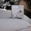
This is the relay I used. Wired as follows: Dk Green/White jumper to #86, 85 to ground. #30 is 12v from a supply. I spliced into the 12v used to supply the controller. #87 goes to the red wire of the controller. It has a diode on 86 to prevent a voltage surge when the brake pedal is released. No voltage is allowed to feed back into the Can bus.
 This is the Dark Green/White wire. I stripped it and soldered a jumper for the relay (#86). It plugs into the white body control module seen in the background. It plugs into the upper right with a strange type of locking mechanism. It is self-explanatory when you see it and move the lever.
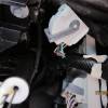 Here is the relay wired in and mounted to the wire loom. At the bottom of the frame you will see I wired in a SP/ST switch. This is to deactivate the brake signal wire when I am not using the controller. I learned this from another vehicle that the relay gives off a clicking sound when the brakes are applied. I can tolerate it when towing, but not always. I drilled a hole in the back wall of the glove box and mounted it there.
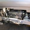
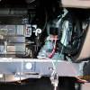 Here is the Prodigy mounted. The area to the left and above the airbag is solid plastic.
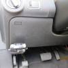
-
Glad to hear you got it on. I think the fitment issue was supposed to be the plastic, but even my 12335 rubs on the rear fascia. Not noticeable and not a big deal.
-
There is a post on this page in which sharkbait8574 states he installed a hitch on his Crossroad. Send him a PM and ask for details.
-
The trailer prep group also has the engine oil cooler that is not standard on a Journey. That is very important because the Journey will run in fourth or fifth gear when towing a load on the highway
The OP cannot have a trailer prep group added at this point. I read from his post that he is interested now in trailer wiring.
BTW, and I have no explanation for this, my SXT DOES NOT have the trailer prep and it does have an engine oil cooler as is listed on the window sticker. I don't recall seeing it as a part of any "group." I do believe that if you are speaking of a TRANSMISSION oil cooler, the 6 speed trans may come with that standard and its easy to check and see it behind the grill.
-
OK, doing some quick math here and I see it would be cheaper to do the wiring yourself. Unknown amount of $$ to the dealer to activate the four wire harness. $65-75 for the add-on four wire factory harness. $$ for your time and inconvienece. I see too much $$ and some PITA.
Go to eTrailer.com and get the 2014 Journey T-One harness (#118536) for $55.95, and spend about 2 hours installing it on some sunny Saturday afternoon.
-
Thanks for that......however, the wobblying for me is happening where the bicycle hitch meets the Curt joint i.e. if you look at my picture, the part where the PIN holds the 2 hitches in place. If it was snug, there will be no wobbly movement
I think I know what you are referring to. I bought a cheaper rack at Menards that had the "wobble." I took it apart at the pivot point and slid some appropriately sized fender washers in there and tighten the bolts. The wobble is nearly gone. I also replaced the pin with a nut/bolt because I rarely open the hatch with a bike on.
-
-
Wait a minute!
I may be wrong on this. If you are just going to do light duty stuff you would want a class II (1 1/4) hitch. That will normally be a 12335. This is the hitch I have on my SXT.
I just looked and I may be wrong about the 13335. I looked up your application and see that there may be an exception on the Crossroad. I have no idea what it may be, but there doesn't seem to be a 13335 or a 12335 hitch listed. The 13335 is a 2" receiver with a normal tow rating of up to 5000lbs. Your 4 cyl. Crossroad would not pull this load and therefore that may be why it is not listing.
I would suggest a call to Curt Tech Support to find the hitch that fits. They, in this case, will know better than me.
If the holes in the frame line up I would think it will fit. If you purchase from Amazon, there is no return fee normally.
-
I put it on mine, $121 from Amazon with free shipping. Install was about 20 minutes with the removal of exhaust hangers.
I don't see why engine would have anything to do with the frame. I am curious as to why they would say no unless it is because the hitch is a class III and your DJ would never be able to pull anything heavy.
-
I just wanted to add to this that just today I finished my install of a Prodigy brake controller. Disregard my other post regarding.
I also wanted to add that it would be a bit of insurance to add a 12v relay with a diode on the positive side of the coil as I did behind the glovebox. Therefore, the Can bus will not be subjected to any voltage spikes when the brake pedal is released and the signal is no longer present.
I tested pulled my 2000k popup today and I barely knew it was back there. I am confident in the DJ as a tow vehicle and even more now that I have brakes.
-
All-
I have figured it out and have my Prodigy brake controller installed. I used the Dk Green/White wire referenced above in the quote by harryj. I used a relay with a diode to prevent a voltage surge and it works perfectly with my Jayco popup. I just got home from my maiden voyage test drive and aside from some brake adjustments all is good.
I did take some photos, if there is enough interest I can do a brief writeup.
-
I think mine went bad, on my cluster it says the outside temp is -17 degrees when it +74. I am compiling a small list for the dealer, but can't bring it in for a simple thermometer problem immediately.
Anybody know exactly what this does?
-
Now I am desperate with this install. I really am not sure how to supply a brake switch feed to the red wire of the Prodigy. I have seen others post how they installed the controller, but never said HOW they accomplished this. Can anyone help me????
I tried following a post by harryj in 2013 where he said this:
Posted 12 May 2013 - 04:57 AM
here some info on wiring 2011 ,i have 2013 planing to do instalation tekonsha P3 but quite shur that you can not hook up to the switch directly, i have not yet did any test yet , But from what i see that you found at the switch ,well i think that look like wire that we need is there on info sheet i have post and link , ... BUT i am verry good at this and i think that the right wire to do this might be at the end of the origenal wire harness dodge or any adapter requiered for trailer , at the end ther is 2 or 3 relays one of them must be for braking light you must only hook up at the end of relay not at the end of the 4 wire plug would be pin #85 or 86 and I would use a second relay there to do the switching of 12volt for the brake controle ,just to be safe , here what i have found or go to http://www.commandoc...andura/629.html
Dodge Journey 2011- IAM planing to do this on my journey some time this week . So i will have the Right spot and Information for this ..!
PART COLOR LOCATION 12 VOLT CONSTANT RED (+) @ BCM, LT.GRAY 4-PIN PLUG(C2), PIN 3, SEE NOTE #2 STARTER LT.BLUE/TAN (+) for STARTER KILL ONLY!! @ BCM, BLACK 24-PIN PLUG(C1), PIN 19, SEE NOTE #2 STARTER 2 PURPLE/LT.BLUE (?) @ KEYLESS IGNITION NODE (START/STOP Button) BLACK 6-PIN PLUG, PIN 4 IGNITION 1 PINK/WHITE (+) @ BCM, BLACK 48-PIN PLUG(C5), PIN 27, SEE NOTE #2 IGNITION 2 N/A IGNITION 3 N/A ACCESSORY/HEATER BLOWER 1 N/A ACCESSORY/HEATER BLOWER 2 N/A KEYSENSE N/A PARKING LIGHTS ( - ) EHITE/BROWN (-) THRU a 1130 Ohm resistor, use a Relay to ISOLATE Switch @ BCM, BLUE 24-PIN PLUG(C7), PIN 20, SEE NOTE #2 PARKING LIGHTS ( + ) SEE NOTE #3 @ BCM, SEE NOTE #2 POWER LOCK PURLE/LT. GREEN (-) THRU a 330 Ohm Resistor will LOCK @ BCM, BLACK 48-PIN PLUG(C6), PIN 23 (without One-Touch up Windows) SEE NOTE #2 POWER UNLOCK using same wire, a (-) THRU a 100 Ohm Resistor will UNLOCK DIAGRAM DOOR TRIGGER PURPLE (-) @ BCM, BLACK 48-PIN PLUG(C6), PIN 25, SEE NOTE #2 DOMELIGHT SUPERVISION YELLOW/PURPLE (+) @ BCM, BLUE 24-PIN PLUG(C7), PIN 14 SEE NOTE #2 TRUNK RELEASE N/A SLIDING POWER DOOR N/A HORN DK.GREEN/WHITE (+) @ BCM, BLACK 24-PIN PLUG(C1), PIN 23, SEE NOTE #2 TACH BROWN/YELLOW, BROWN/DK.BLUE, BROWN/LT.BLUE, BROWN/TAN, BROWN/ORANGE or BROWN/PURPLE (AC) @ Any FUEL-INJECTOR, 2-PIN PLUG, PIN 2 WAIT TO START LIGHT N/A BRAKE DK.GREEN/WHITE (+) @ BCM, WHITE 24-PIN PLUG(C4), PIN 18, SEE NOTE #2 FACTORY ALARM DISARM N/A ANTI-THEFT NO INFORMATION AT THIS TIME!! See NOTE #1
EXTRA INFORMATION NOTE #1: There is NO INFORMATION on the ANTI-THEFT SYSTEM or an INTERFACE BYPASS MODULE for this vehicle AT THIS TIME!! NOTE #2: The BCM is located Behind the GLOVE BOX. NOTE #3: The LEFT FRONT Parkinglight wire is a WHITE/BROWN (+) @ BCM, BLACK 24-PIN PLUG(C1) PIN 4, the RIGHT FRONT Parking light wire is a WHITE/ORANGE (+) @ BCM, WHITE 24-PIN PLUG(C4) PIN 3, the LEFT REAR Parking light wire is a WHITE/GRAY (+) @ BCM, BLACK 48-PIN PLUG(C6) PIN 32 and the RIGHT REAR Parking light wire is a WHITE/ORANGE (+) @ BCM, BLACK 48-PIN PLUG(C5) PIN 4, when connecting use a
Edited by harry.j, 12 May 2013 - 05:05 AM.
I found the Dark Green/White wire in the connector behind the glove box. While the brake pedal is depressed there is 13.38 volts present. Brake pedal in the resting position gives me .20 volts. Is this it? I don't know and I don't know who I can ask. I'm sure the Dodge dealer probably can't help me. Are there any 12 volt electrical geniuses that can tell me if I could use a relay to power the red brake signal wire. Will a relay attempt to energize at a voltage of .20?
I will accept any suggestions here. I am towing a popup at almost 2k lbs. and it is so much easier to stop with trailer brakes.
-
Thanks I will give it a try.
-
I have this: http://www.etrailer.com/Hitch-Cargo-Carrier/Pro-Series/6500.html.
The manufacturer seems to be different now, but it was labeled Draw-tite when I bought mine. It is very solid and the front and back long side rails are one piece, not welded or bolted in the center. Capacity is 300 lbs. which is the tongue weight max for a 1 1/4 hitch receiver.
Curt is also a known quality brand.
-
Looks nice.
I have a can of black plastidip waiting to be tapped. I was going to dip the silver colored area on the lower valance.
If properly applied, is this area going to hold up to washes, rockchips, winter salt/ice, etc.?
-
Is this on a 2014? Wouldn't doing something like this affect your warranty? Also, I would think the loss of backpressure would affect factory set system specs. in the engine and emission controls.
- Eric Evans and Rgwog
-
 2
2
Brake controller
in Accessories, Modifications
Posted
Search my posts in the hauling section for a mini tutorial. I installed a Prodigy brake controller and I pull (and stop) a 2000# popup just fine.